

The tool bar is located at the top of the interface. It offers tools for editing objects in the drawing.
The tool bar contains the following tool functions:
These tools are complemented by other choices that appear in the middle and right of the tool bar, depending on the tool.
The basic settings of the tool bar is the tool Select.

After you select the New Object tool, six different options for inserting new objects in a drawing appear to the right of it.

| Option | Name | Definition |
|---|---|---|
| 1 | Symbol | Symbols can refer to various objects, such as constructive or electrical elements. |
| 2 | GDTF | The "General Device Type Format" is a format that creates a uniform data exchange definition for the operation of intelligent illumination devices such as "Moving Lights". |
| 3 | Mesh | 3D Mesh Files are files with no further properties; only 3D geometries are displayed to represent the surface of an object. |
| 4 | Connection | Connection can be used to establish connections between structural elements. These are necessary for load calculation. |
| 5 | Dimension | These are Dimensions that can be inserted into the Renderer. |
| 6 | Assembly Group | The Assembly Group represents a freely defined assembly of objects. |
There are three different libraries from which GDTFs, meshes and symbols can be inserted:
Open Documents shows all objects already included in opened drawings or that have been created in them.
Local Resources, which refer to the individual resources of the respective user, are thus stored on his computer and available in offline mode.
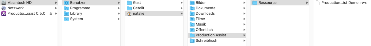
You can add files (".lrwx files") to your library folder on your own by storing them in the following file path:
-> User/username/Production Assist/Resource
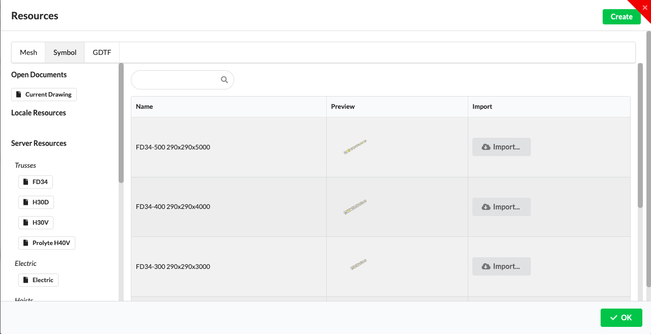
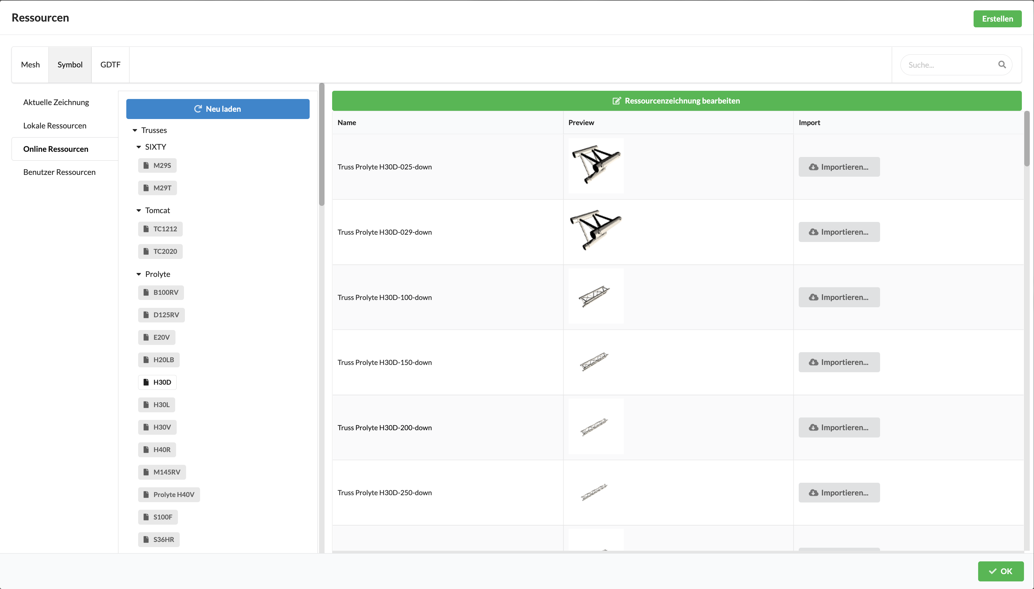
Global resources, i.e., server resources, are available online from the Production Assist Server. Here, individually generated online resources for each user are also stored and made available.
The libraries are sorted by object areas such as Fixtures, Power or Truss and have subfolders designating the different manufacturers or object types.
The Assembly Group option creates an empty Assembly Group in the Renderer and Scene Tree, to which you can then add objects. You can also create Assembly Groups by selecting the desired objects in the Renderer or Scene Tree and using the Group Selected Objects command in the context menu.
To insert resources, select the desired option in the tool bar. The Resource Window opens. Select the corresponding object from the various sources and click on the grey Import button to the right of it.
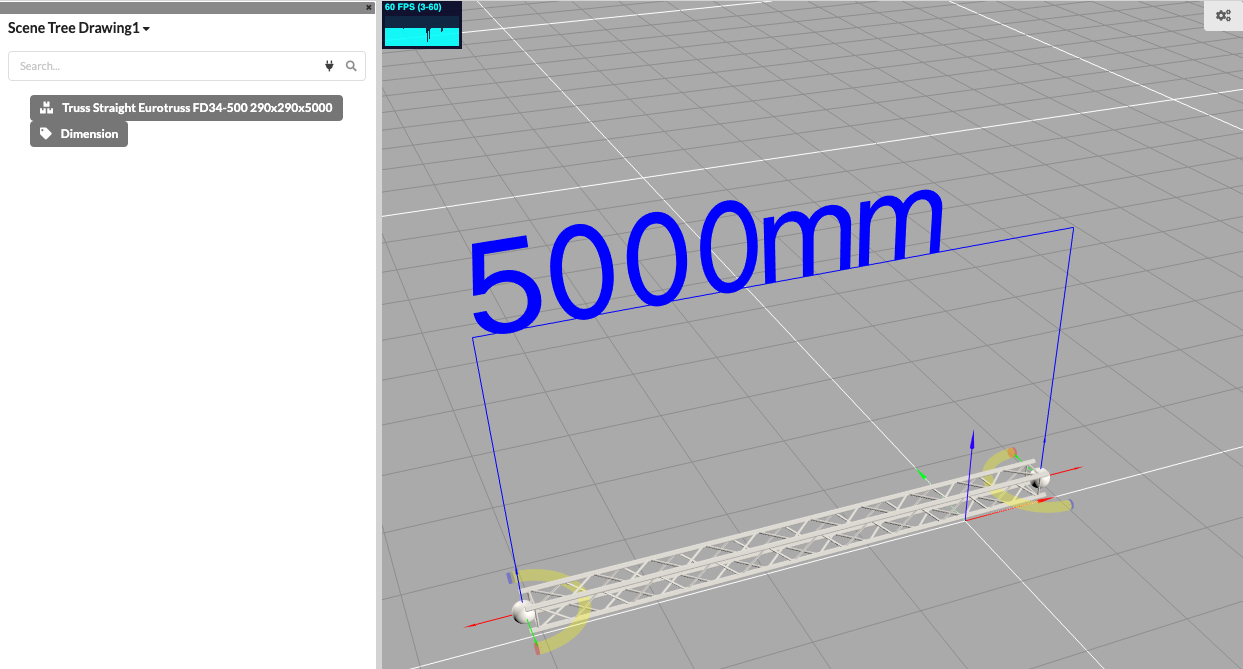
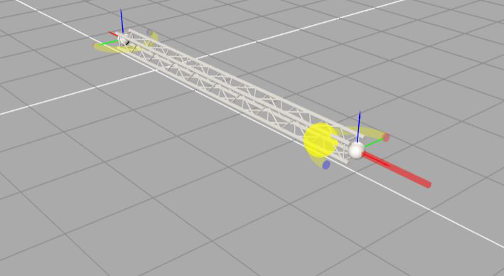
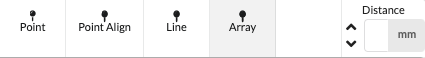
The cursor jumps back into the Renderer and marks the location of the insertion point yellow. With a mouse click you can now place your object where you want. Clicking again inserts additional objects with the same properties. In addition to the possibility of inserting each object individually into your drawing, you can also insert several objects simultaneously with one click. To do this, select among the insertion options on the far right of the toolbar: Point, Point Align, Line and Array. With "Point Align" you can rotate the object directly around the z-axis when inserting, with "Line" you can also set the distance between the objects to be inserted on the far right in the Distance field. The "Array" option allows you to insert specific objects such as Curtains along a path.
To detach the object from the mouse, press the "X" key, and then you can select and insert more objects in the same way.
With traverses there are yellow magnets at the start and end points. These allow trusses to be easily docked together and thus ensure quick assembly of truss lines or a more complex structure. To do this, hold your mouse pointer over the end of the existing traverse. The new traverse to be inserted is now displayed. By pressing the shift key, you can now rotate the traverse to be inserted around its axis. By pressing the control button ( Control ), you can switch between the magnets of the traverse to be inserted. A left click now inserts the traverse.
This tool allows you to insert dimensions in the Renderer. To do this, click on the two end points to which you want to apply the dimension.
coming soon...
Using the Select tool displays six options for selecting an icon in the Scene Tree or Renderer. Selected objects are highlighted in red.
| Option | Name | Definition |
|---|---|---|
| 1 | Single | Individual objects are selected. Multiple selection is possible by holding down the SHIFT key – for selection of consecutive objects - or the CTRL key (Windows) or CMD (MacOS) – to select different objects. |
| 2 | Same Name | The selection is applied to all objects that have the same name. |
| 3 | Same Resource | The selection includes all objects with the same symbol definition. |
| 4 | Same Class | The selection includes all objects that are stored in the same class. |
| 5 | Same Layer | The selection includes all objects that have been placed on the same layer. |
| 6 | Box | The selection captures all objects within a box or rectangle placed around them in the Renderer. You can place the box freely in the 3D renderer with a mouse click. |
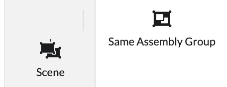
In addition, options 2-4 allow you to determine whether only the same objects within the corresponding assembly group or the entire drawing (Scene) should be selected.
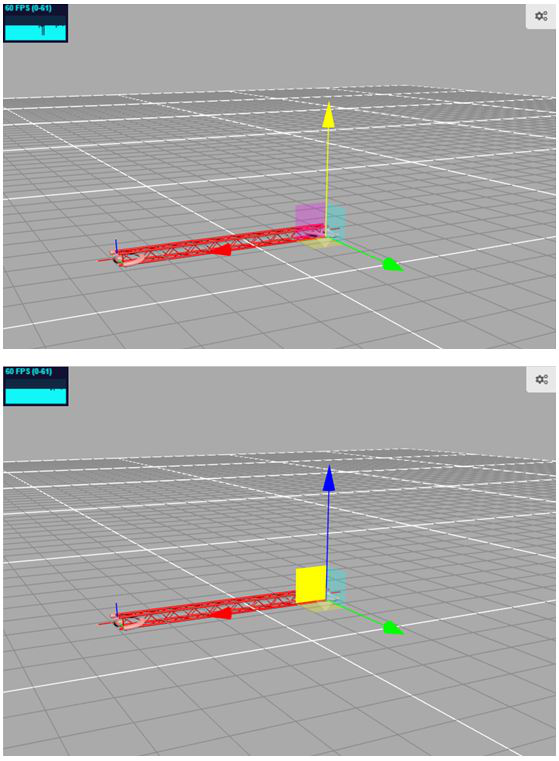
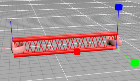
The Move tool moves all selected objects in the Renderer by clicking and holding down the mouse button on either an arrow of the X, Y, Z coordinate system or the square plane between the arrows in the Renderer. The selected arrows or area turns yellow.
When translating, you also have the choice of whether you want to translate the selected object along the drawing axis (global) or along the object axis (local) . This is useful when the object is angled due to rotation.
Move global 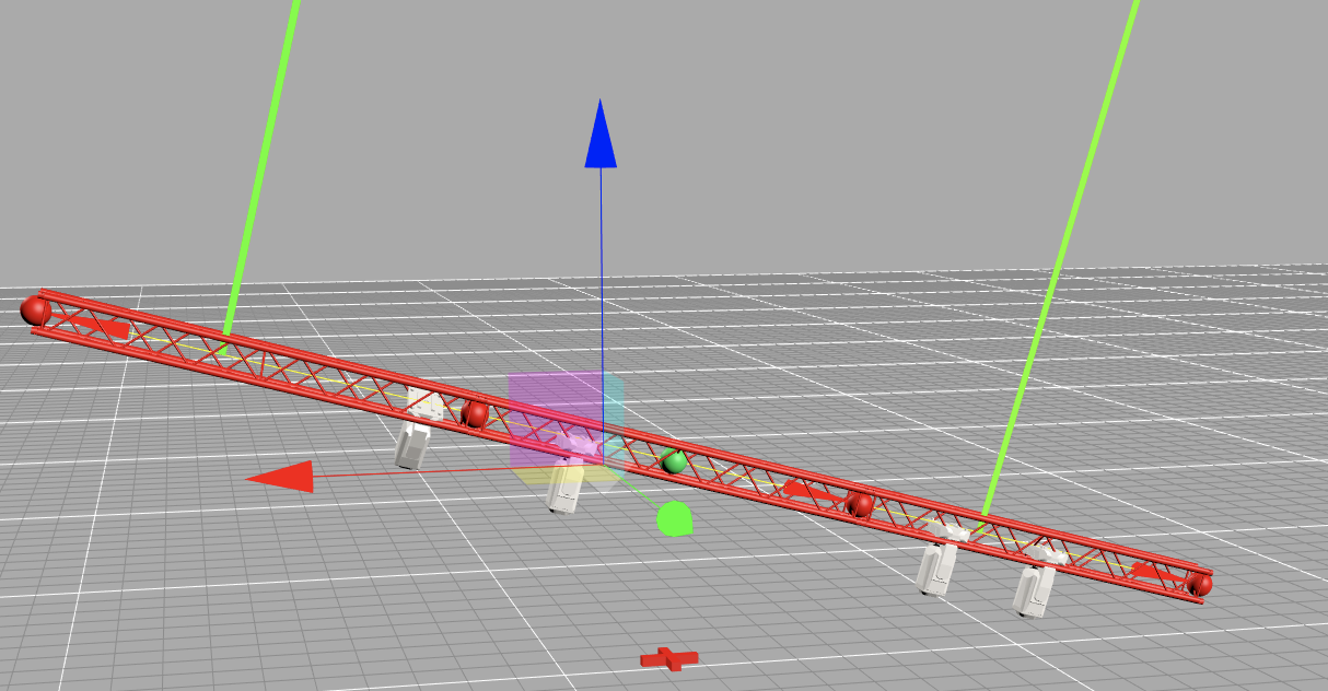
Move local 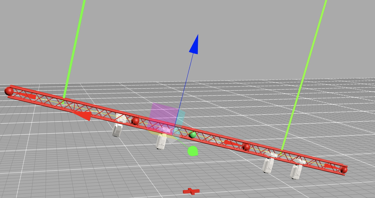
In order to precisely connect a selected object with an unselected object at their respective magnets (comparable to the haptics of connecting magnets with different polarity), you can work precisely by using of the Move tool and holding down the Cmd key (for MacOS) or the Ctrl key (for Windows).
With the Scale tool, all selected objects can be scaled to a desired size in any direction of the X, Y, Z coordinate system.
When scaling, you also have the choice of whether you want to scale the selected object along the drawing axis (global) or along the object axis (local) . This is useful when the object is angled due to rotation.
Scale global 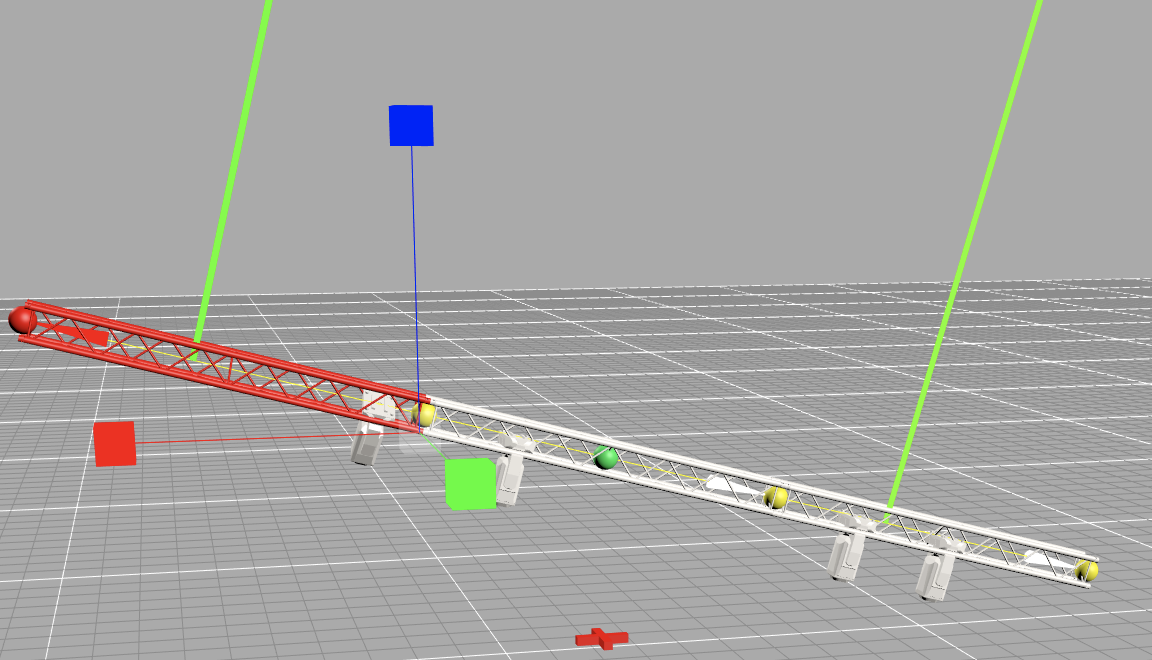
Scale local 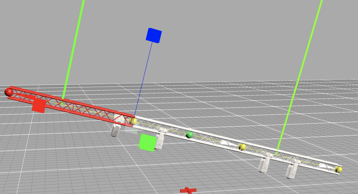
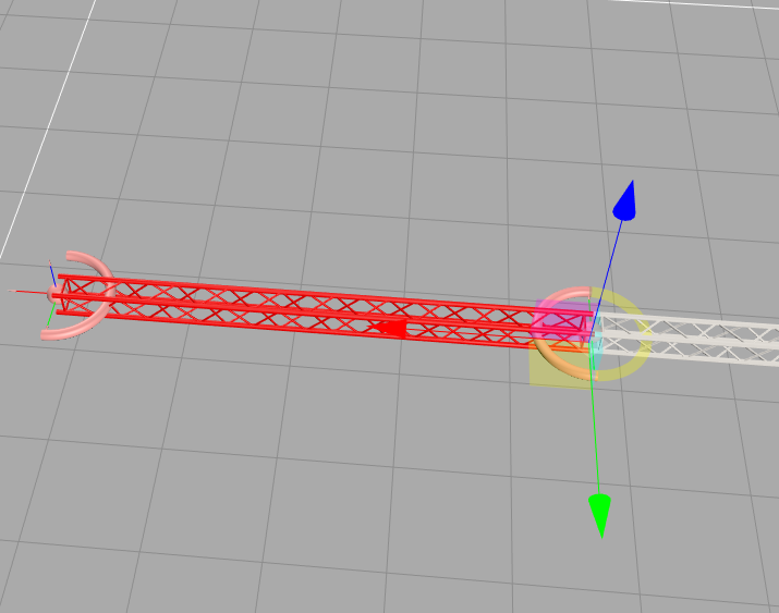
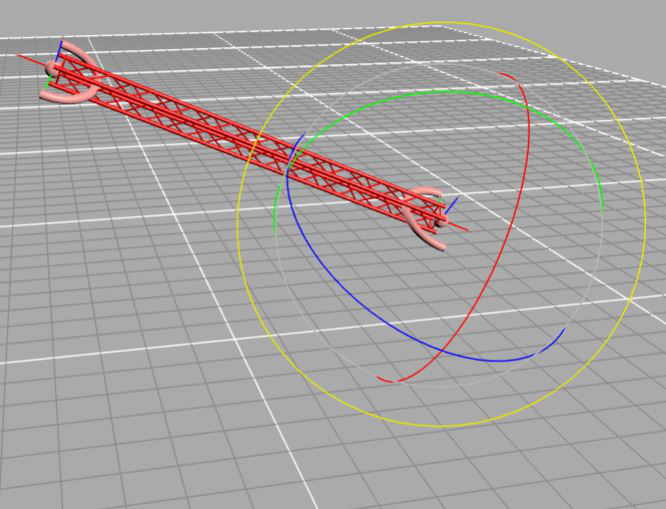
With the Rotate tool, all selected objects can be rotated in any desired X, Y, Z circular direction. It always rotates around the insertion point of the object.
When rotating, you also have the choice of whether you want to rotate the selected object along the drawing axis ( global) or along the object axis (local) . This is useful when the object is already angled from a previous rotation. You can also cycle through different anchor points during rotation by pressing the Control key.
Rotate global 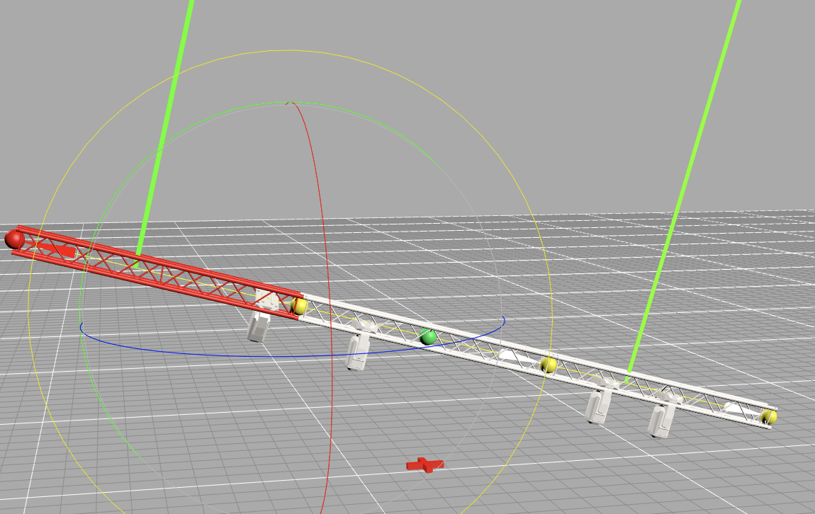
Rotate local 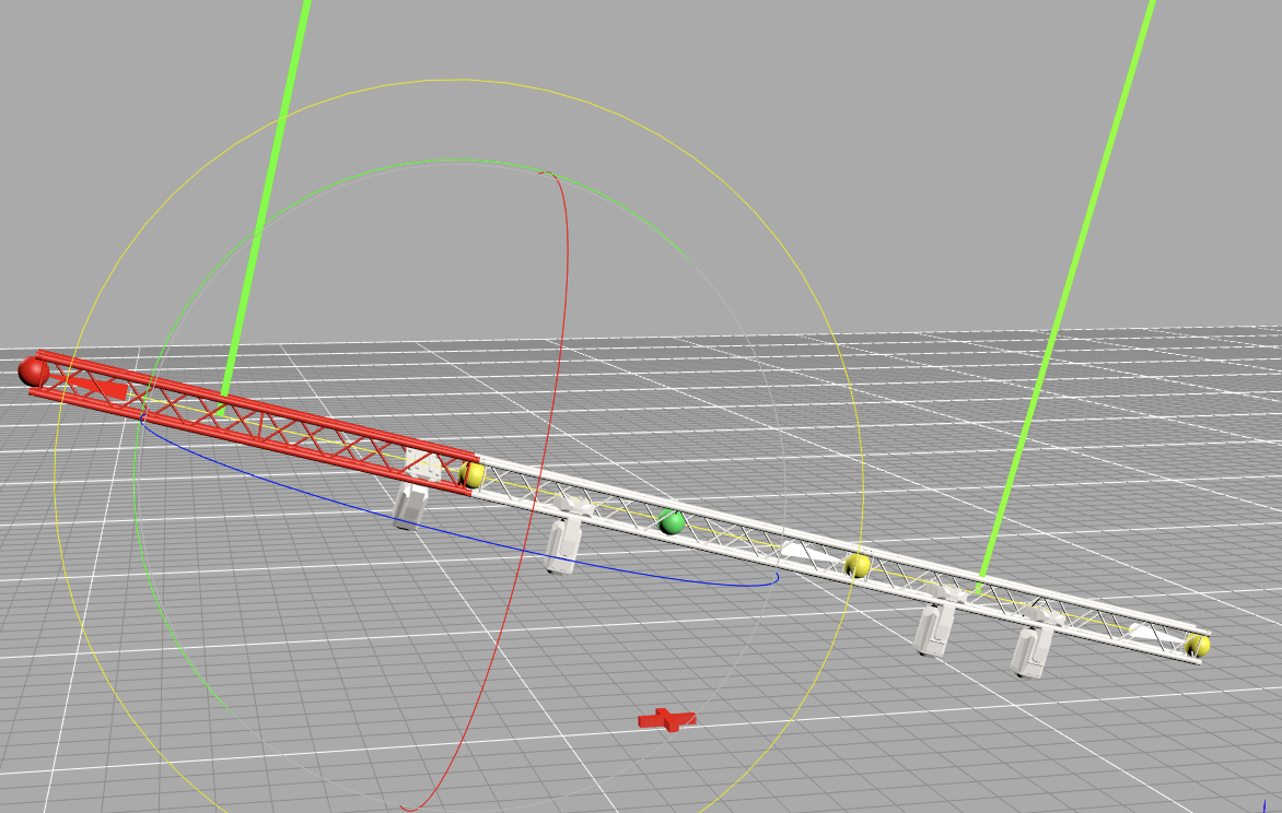
You can use the Align tool to align objects. There are two variants.
With the Light option, you align selected spotlights to a focus point that you can set in any desired direction of the X, Y, Z coordinate system.
The Assembly Group Origin option allows you to realign/move the zero point of an assembly group. all position coordinates of the assembly refer to this zero point.
With the Orbit tool you can move the view of the plan in the 3D Renderer view as desired. This tool is especially useful if you're working on a tablet and can't use a trackpad or mouse to move objects around in the plan.
With the Measure tool you can measure lengths between two selected points. To do this, simply click on the desired points. You end measuring by pressing the "X" or ESC key.
The Mirror tool gives you the ability to mirror objects. To do this, simply activate the desired object, then click on the tool and draw the mirror axis on which you want to mirror with two points.