

Many different symbols can be inserted into a drawing. If necessary, they can be edited in the Edit mode of the program.
Symbol definitions (symbols) are intelligent objects that consist, for example, of geometries and other objects such as electrical connections and similar objects.
Fixtures are symbols containing additional spotlight light information.
GDTF stands for "General Device Type Format". This is a uniform data exchange format between intelligent spotlights, CAD programs and visualizers. In this format, all the properties of a spotlight are described in detail. Once defined by the spotlight manufacturers for each lamp type, each software uses the same information about data, geometries and control. This drastically simplifies data exchange. GDTF is an open source format. GDTFs can be imported and are then automatically converted by Production Assist to Fixtures and stored in the Resource Manager.
To optimize the functionality and performance of Production Assist, imported symbols from MVR files can be replaced by Production Assist symbols. An import dialog for this is already available when importing the MVR. In addition, the mapping - i.e. the specification of which symbol should be replaced with which Production Assist symbol - can be viewed, supplemented or deleted in the Resource Manager.
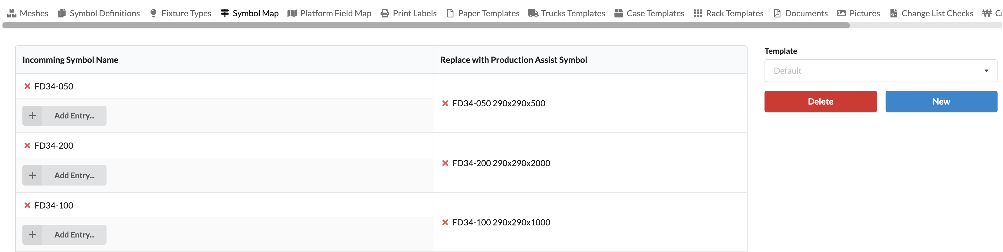
In the left area of the window you can see which mappings have already been created. You can delete them by clicking on the red X in front of the symbol names. New exchange templates can be created via Add Entry.
A window opens in which the symbol (Incoming Symbol Name) to be replaced and the replacing symbol (Replace with Production Assist Symbol) must be selected.
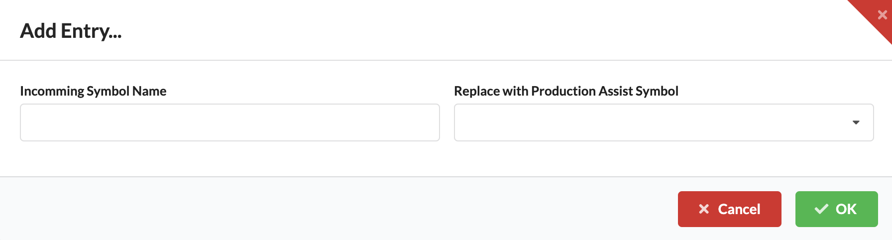
Upon the next import, this selection will already be set in the import dialog.
On the right side of the window, templates for Symbol Maps can be created and deleted. To do this, create a new template via New and adjust it on the left side. Each change is written to the currently selected template. You can then retrieve repeatedly in the list later.
This helps, for example, if you get files from different customers that need to be replaced differently.
Delete can also be used to remove unnecessary templates.
Symbols are managed in libraries. There are currently three different libraries:
Drawing Library - shows all objects that are already in the current drawings.
Local User Library - shows the individual resources of the respective user, which are stored on his computer and thus available offline.
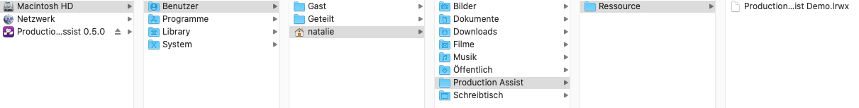
You can add files (".lrwx files") to your library folder on your own by placing them in the following file path:
-> User/Username/Production Assist/Resource
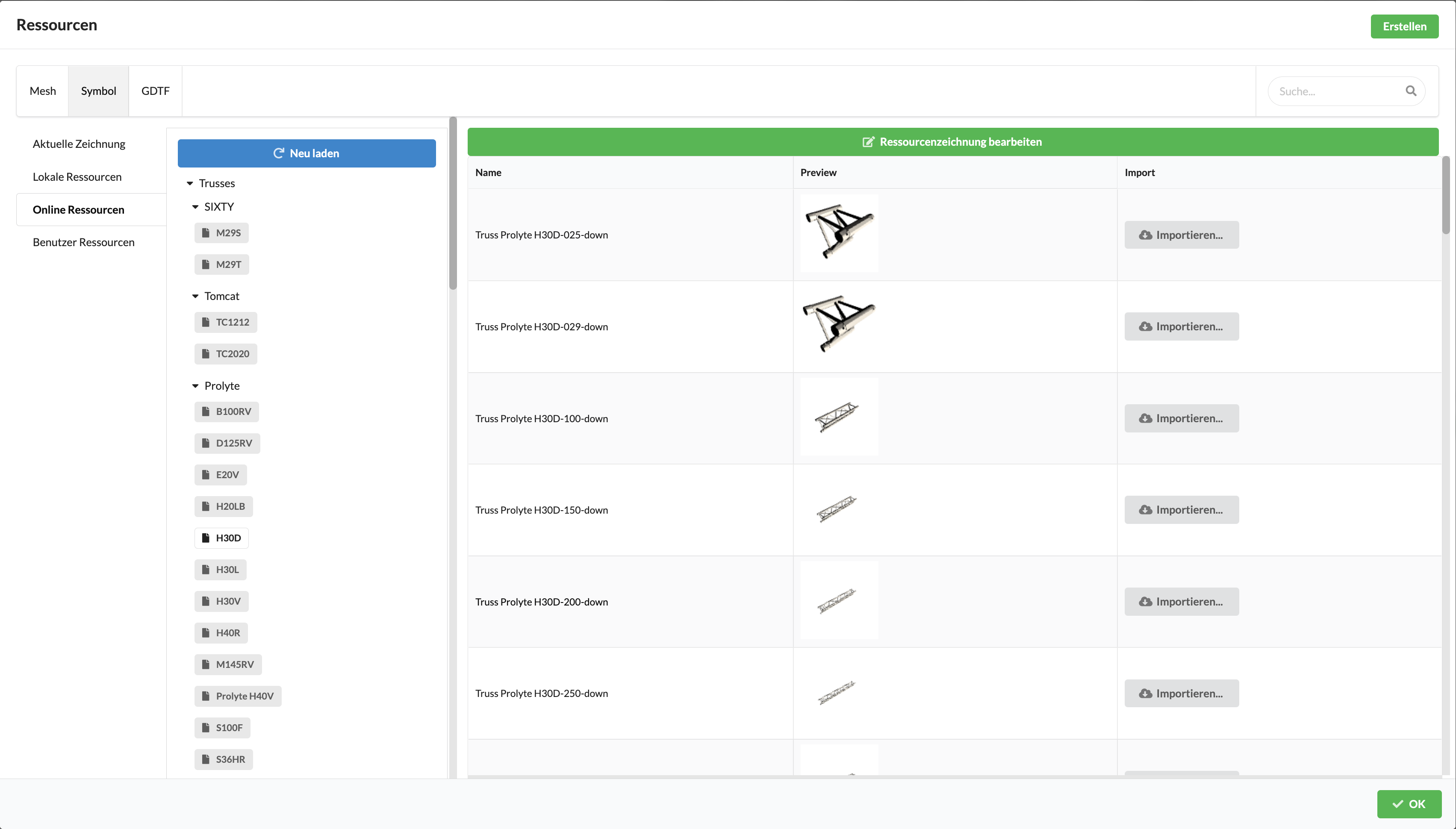
The Online Production Assist Server Library. Here you will find all the resources that have been created and made available by Production Assist.
The libraries are sorted by object areas such as Fixtures, Power or Truss, and have subfolders containing the different manufacturers or object types.
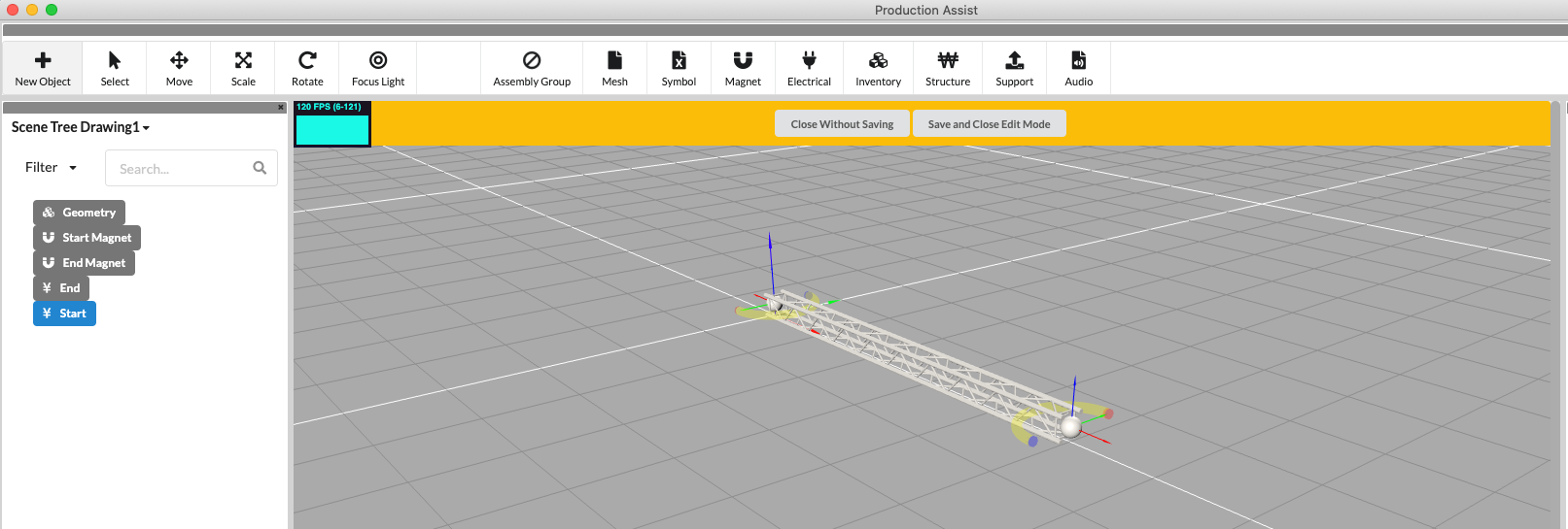
In order to edit a symbol and to switch to Edit mode, there are two different options:
The Renderer switches to Edit mode and opens the Edit Geometry window with a wide yellow bar at the top. There you also have the option of leaving the mode by saving or discarding the changes.
You will now see the elements contained in the Scene Tree. You can click on them and delete them, rename them or edit their Object Properties. You can also add new items using the New Object tool in the Toolbar.
When everything is ready, click Save and Close Edit Mode in the yellow bar at the top of the Renderer.
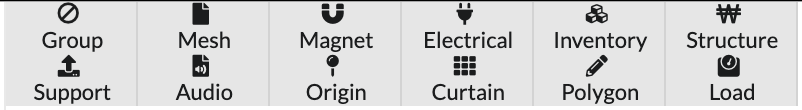
The New Object tool displays twelve options for inserting new geometries into a symbol definition. "Assembly Groups", "Meshes", "Magnets", "Electricals", "Inventories", "Structures", "Supports", "Audios", "Origins", "Curtains", "Polygons" and "Loads" can be inserted.
| Name | Definition |
|---|---|
| Group | The Assembly Group represents a freely defined assembly. |
| Mesh | These elements are geometries without further properties that merely represent the surface of a three-dimensional object. |
| Magnet | These elements are used to define insertion points that are used to make objects snap together like magnets when drawing. Thus, it is possible to assemble a truss line or a more complex structure relatively quickly. |
| Electrical | These elements are used to define power connections (connection cables) in the symbol. |
| Inventory | These elements are used to define accessories within a symbol that are later also displayed in the inventory list. |
| Structure | These elements can be used to add calculation data such as cross-sections. This calculation data is necessary for static calculations. |
| Support | With these elements, hoist characteristics such as chain cross-section and load capacity can be added. This data is necessary for static calculations. |
| Audio | These elements mark symbol definitions as audio objects. |
| Origin | These elements are used to mark the insertion points of objects. |
| Curtain | |
| Polygon | These elements will be used to add two-dimensional objects. |
| Load | These elements add loads to the icon. |
Mesh geometries are mainly used to add a 3D object to the symbol and thus make it visible.
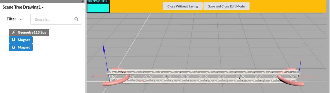
By inserting magnet geometries into a symbol definition, you can create the insertion points for snapping for a new object. This is most often applied to truss symbols. The magnets are placed at the start and end points of the symbol definition.
By inserting electrical geometries, connections (connection cables) called "wires” are added to a symbol definition. This makes it possible to add inputs and outputs to a geometry.
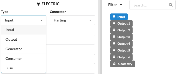
In the example below, you can see a plugbox named HAN16. A total of seven electrical connectors (wires) are added to this geometry, consisting of one input and six outputs. Each selected wire can be freely named by clicking in the “Name” column in the object properties of the Edit Geometry windows . In this example, the seven connection lines were named Input, Output 1, Output 2, Output 3, Output 4, Output 4, Output 5, and Output 6.
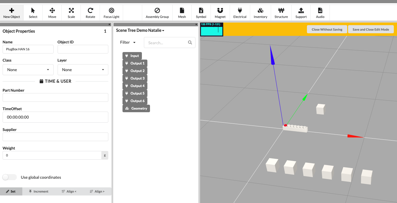
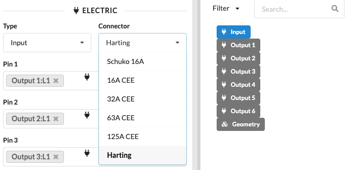
In the Object Properties, the assignment of the connection mode and type can also be specified for each electrical connection. Here in the example, the connection type of the wire is an input and the connector - i.e. the connection type - is a Harting connector.
Other choices for the connector include: "Schuko 16 A", "16A CEE", "32A CEE", "63A CEE" and "125A CEE".
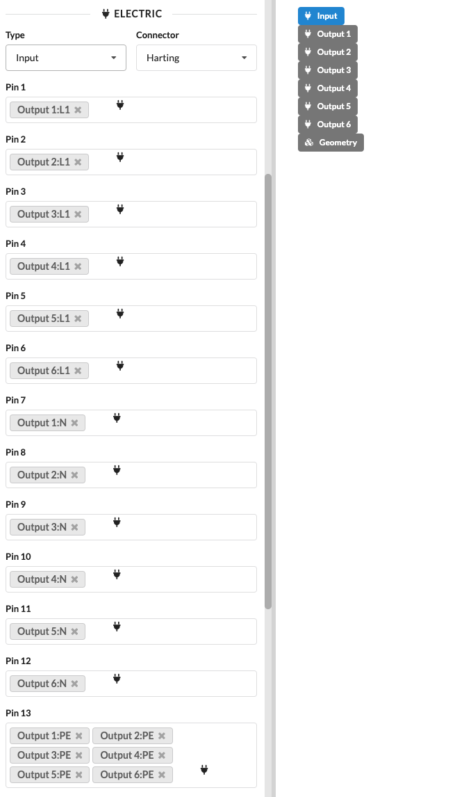
Depending on the selection of the Type and the Connector, the Electric section displays corresponding phases and conductors that you must connect accordingly. Here in the example you can see the assignment of the input pins of the PlugBox HAN16, the phase "L1", the neutral conductor "N" and the grounding "PE".
Depending on the type of port a symbol has, it is assigned to one of the following three device types:
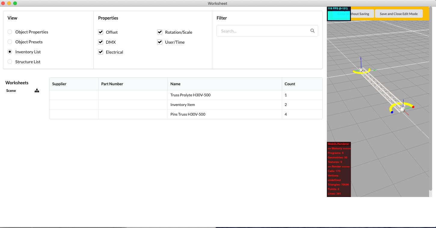
By inserting an inventory geometry, accessories, so-called Inventory Items, can be created. Each selected Inventory Item can be freely named in its Object Properties in the Name field. In this example, one of the two Inventory Elements was named "Pins Truss H30V-500". Under "Time & User" in the Object Properties, you can specify the number of desired elements of the Inventory Item under Count. Here in the example, the Count is set to the number 4.
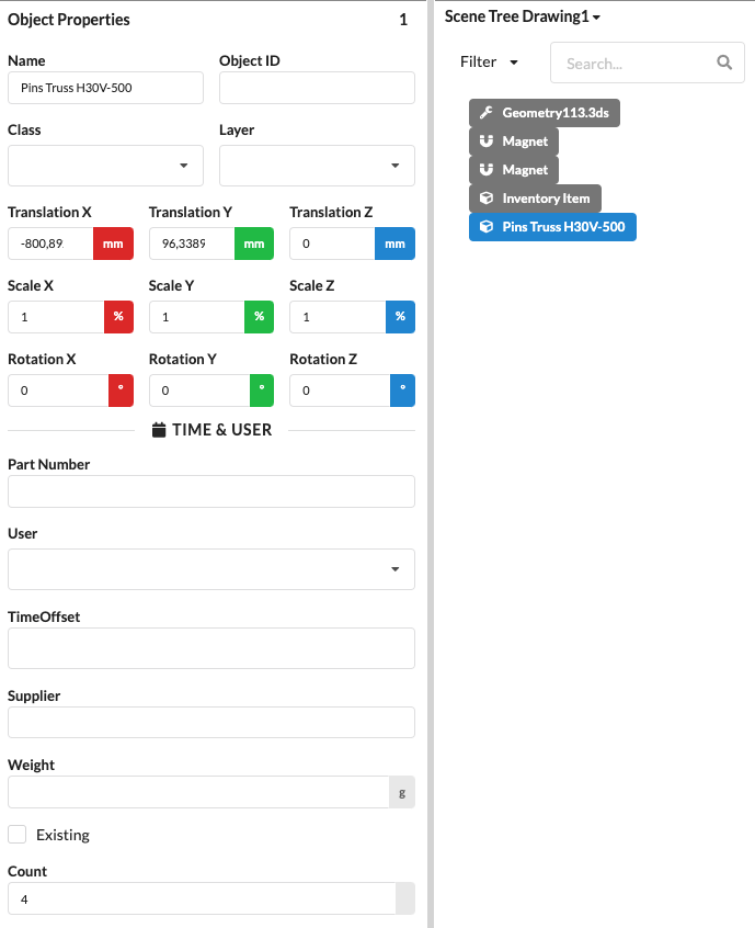
The created Inventory Items are listed in the Object Properties of the symbol in the drawing, and their number can also be changed there. They also appear in the Inventory List of the Worksheet. To do this, however, the Show Accessories option box must be selected in the filter area.
By inserting structural geometries into a symbol, structural data such as cross-sectional data can be assigned. This is necessary for static calculations.
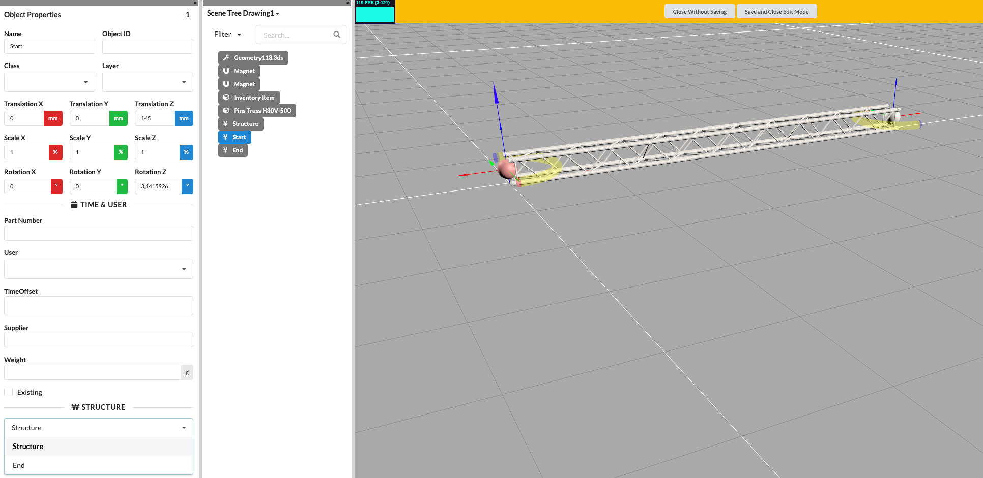
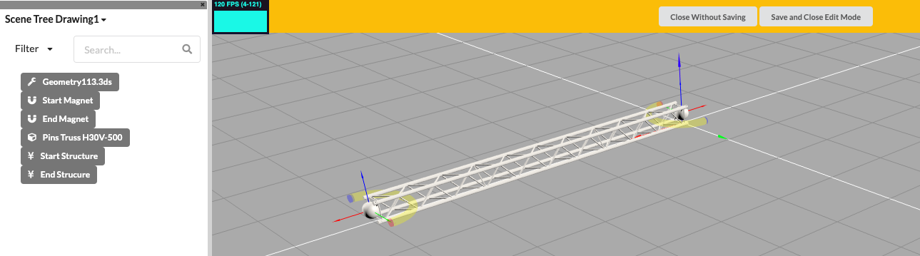
A structural symbol, such as a truss, which is designed to be connected to several objects, requires both structural geometries (start and end structure points) and magnet geometries (start and end magnets) to enable connections by means of snapping.
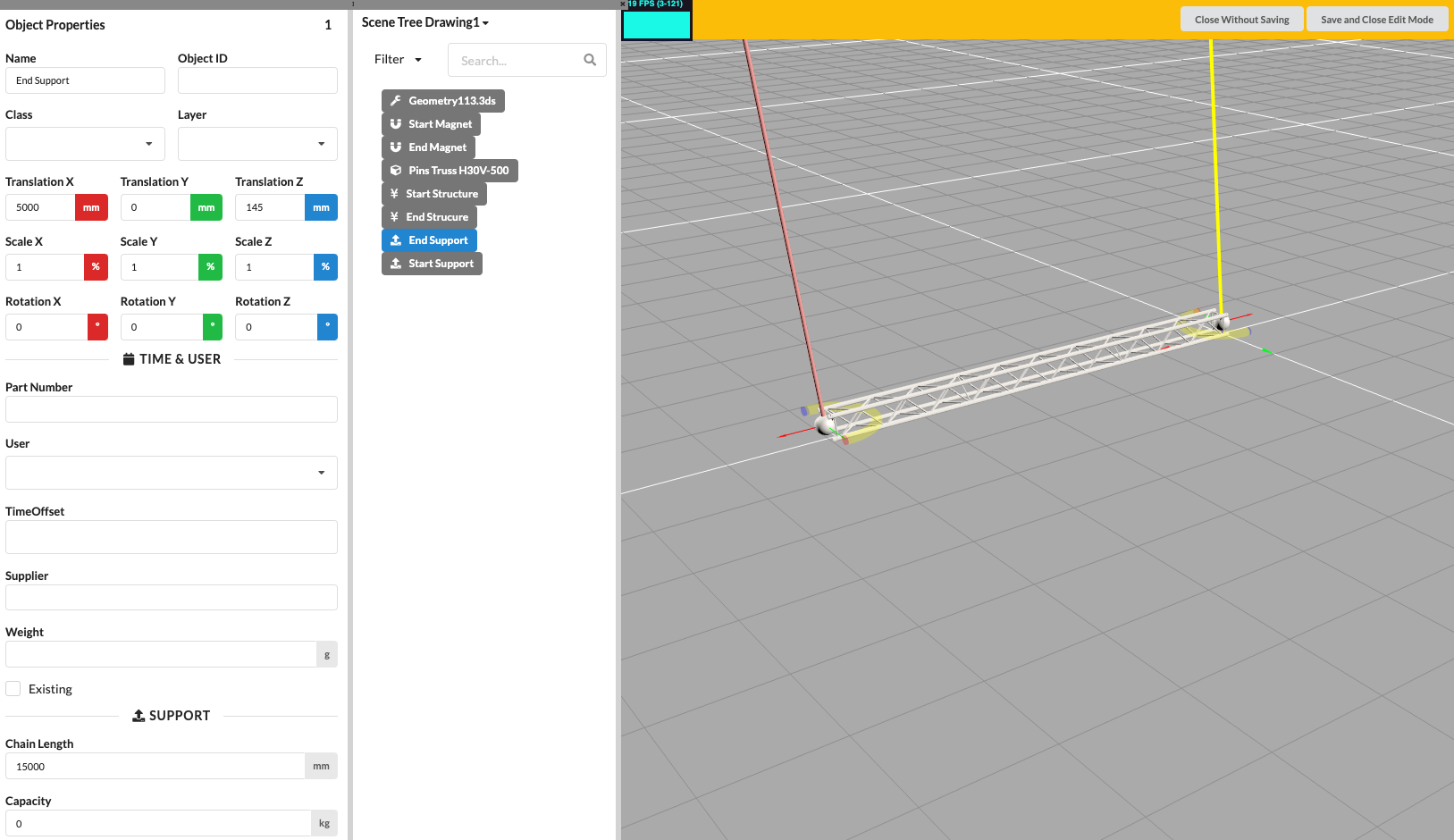
By inserting support geometries into a symbol definition, the start and end points for the load bearing capacity of a new object can be defined, e.g., for chain hoists or supports.
The support geometries are placed at the start and end points of the symbol. In the Object Properties under the item Support, the chain length and the (capacity) can then be determined.
Inserting audio geometries into a symbol definition defines the origin of an audio source. This also automatically makes the object an audio object.
Load geometries allows a symbol to define where which load acts.
XXXX - überflüssige Texte?
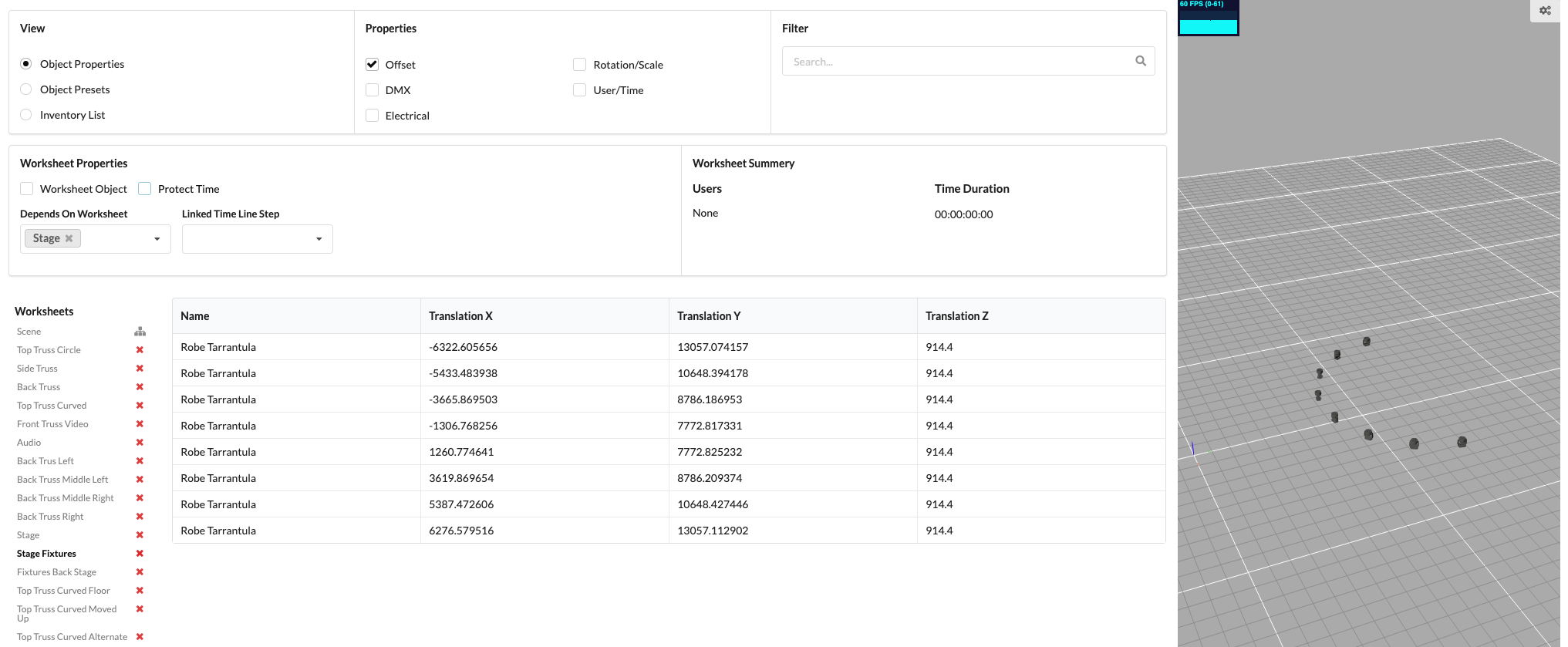
In order to create a worksheet, i.e. a worksheet, of the imported objects in a project, you can select option “Worksheet” under menu item “Window” can be selected. The Worksheet window opens, which contains three different worksheet overviews (“views”); the “Object Properties”, “Object Presets” and “Inventory List” view.
Various information about the object properties, known as “properties” , can be switched on in each view. Possible properties are “offset”, “DMX”, “electrical”, “rotation/scale” and “user/time”. Depending on the connection of the different properties, you will receive different information in the worksheet.
It is also possible to search for objects in the worksheets under line “Filter” . All created worksheets are listed under “Worksheets” in the worksheet window and can be deleted there by pressing the “X” button highlighted in red. The 3D renderer window, which is right aligned in the worksheet window, provides an overview of the selected worksheet.
A selected worksheet can be set in “Worksheet Properties” depending on other worksheets. The lines under “Depends On Worksheet” and “Linked Time Line Step” are available for this purpose.
TODO: Deal with it here, in a later development step.
Tick the checkmark “Worksheet Object” ... Tick the box at “Protect Time” ...
Under “Worksheet Summary” you can find the information of the user involved in the worksheet and the time duration, i.e. the length of the the timing of the respective worksheet.
TODO: “Worksheet Properties” and “Depends On Worksheet” and “Linked Time Line Step” in a later development step.
TODO: Support geometries, revise in a later development step.
TODO: Currently wildcards. In a later development step, go into audio.