

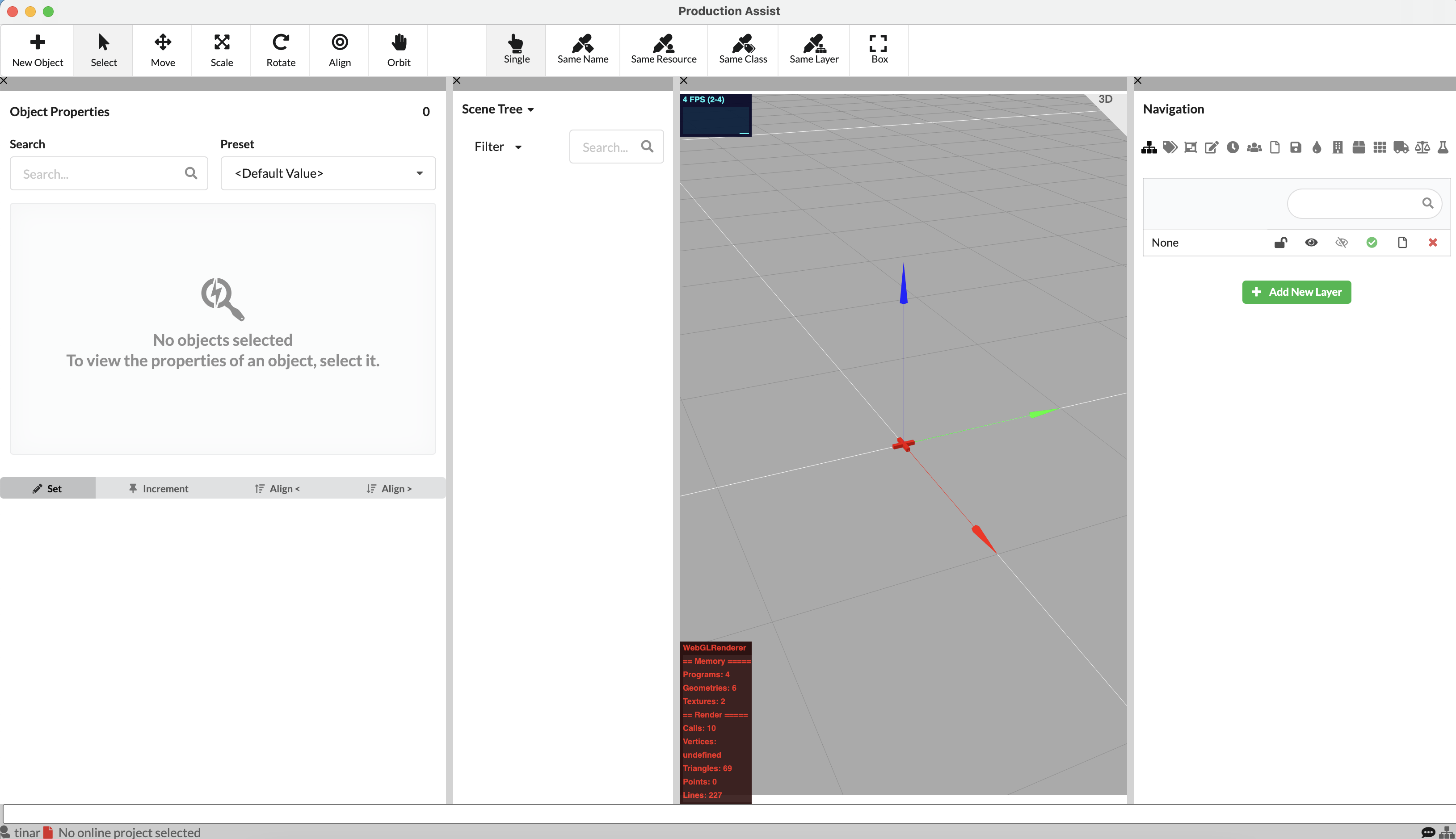
A brief overview of the different areas and what can be found there is summarized in the chapter User interface
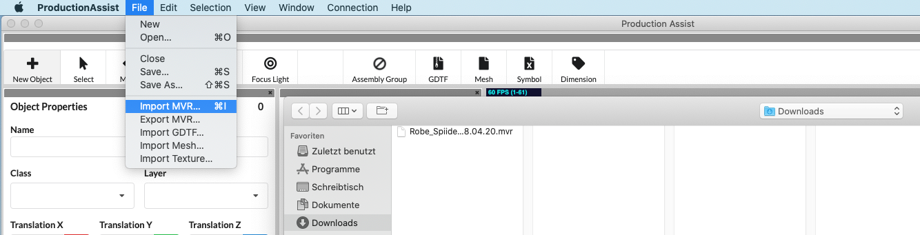
On the menu bar under File, click Import MVR and select the MVR file to be imported onto your computer.
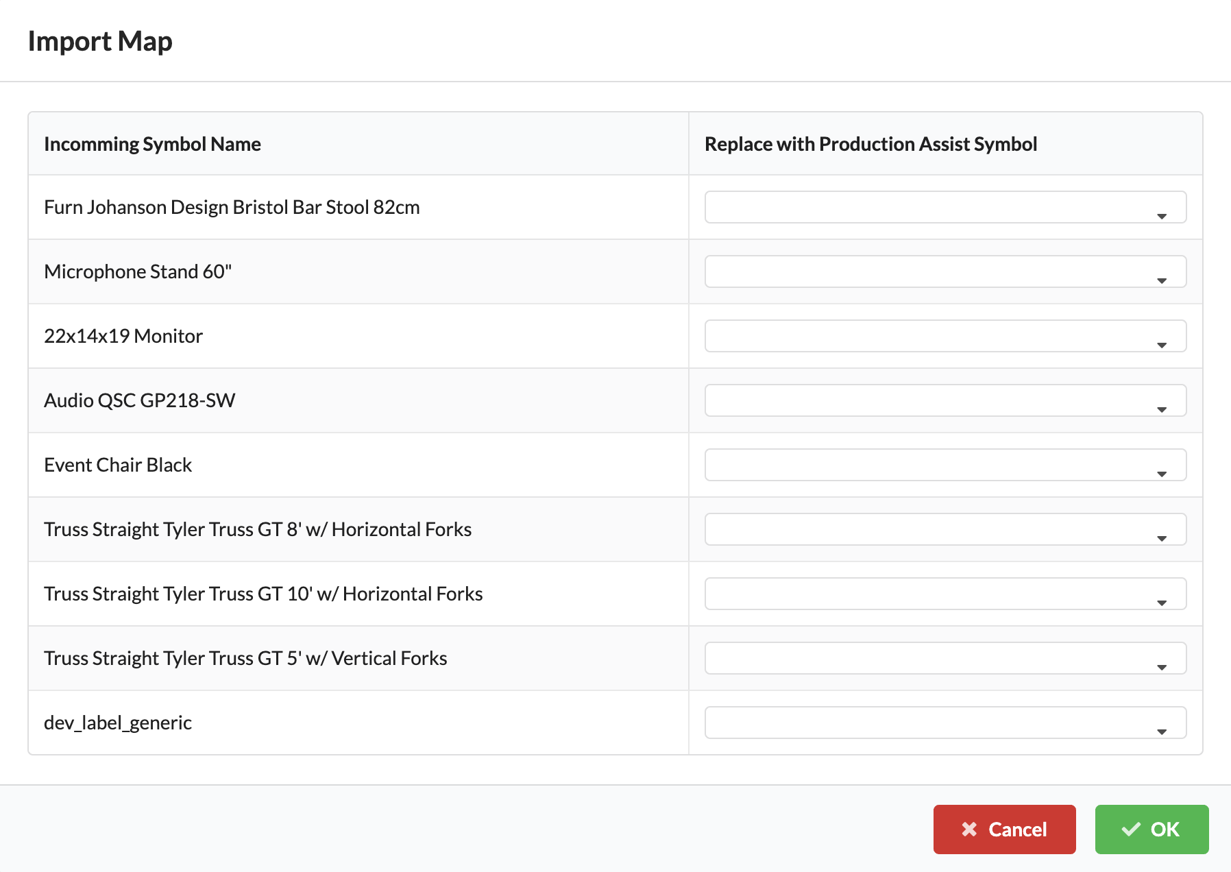
A window will open – this is the Import Map. Here you will see all the symbols that Production Assist has found in MVR. You now have the option to replace them with symbols from the Production Assist Library. This can eventually improve the functionality of Production Assist if, for example, not all the necessary information was available in the MVR symbols.
You can also continue without replacing symbols and take care of this later if necessary.
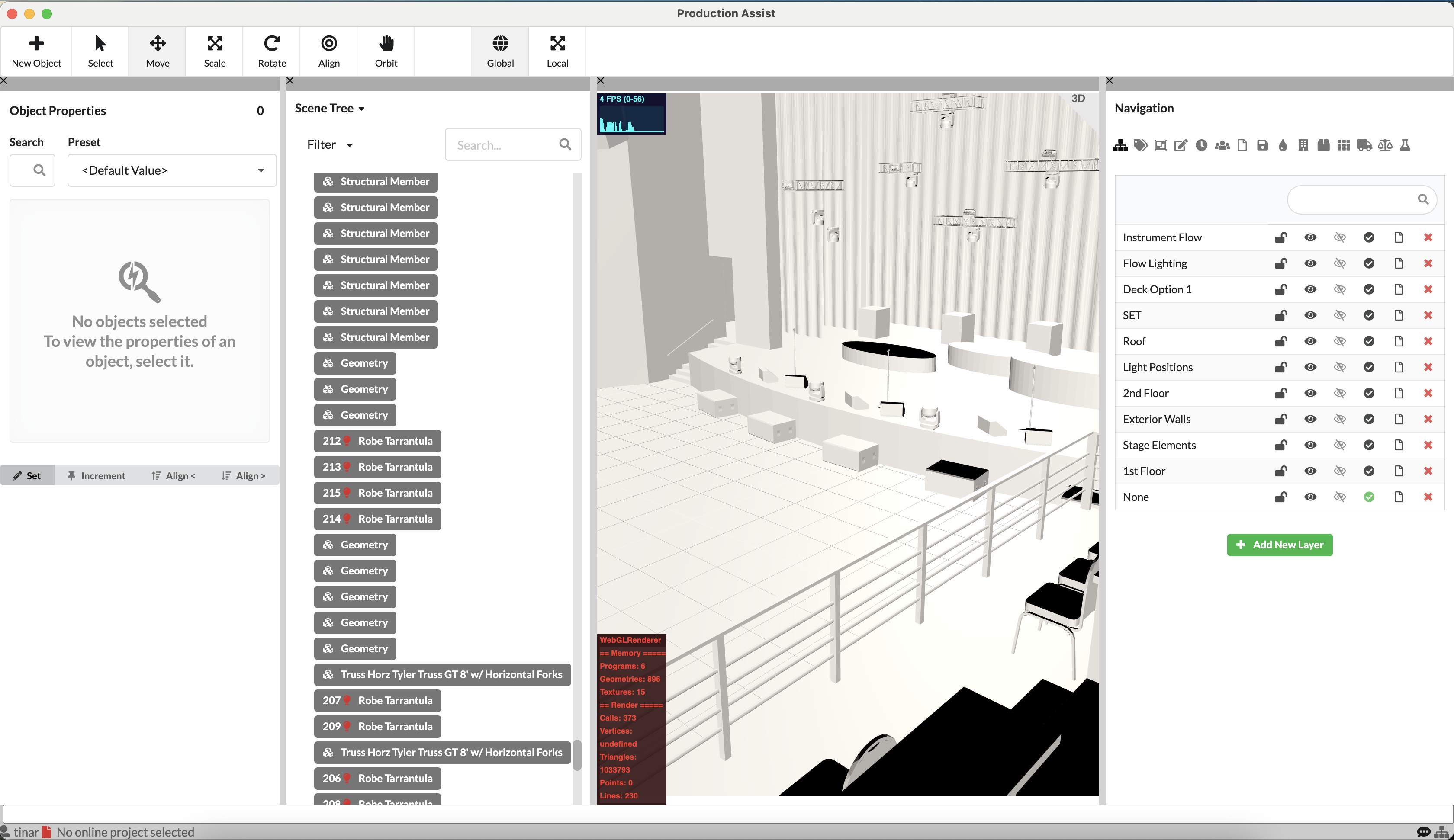
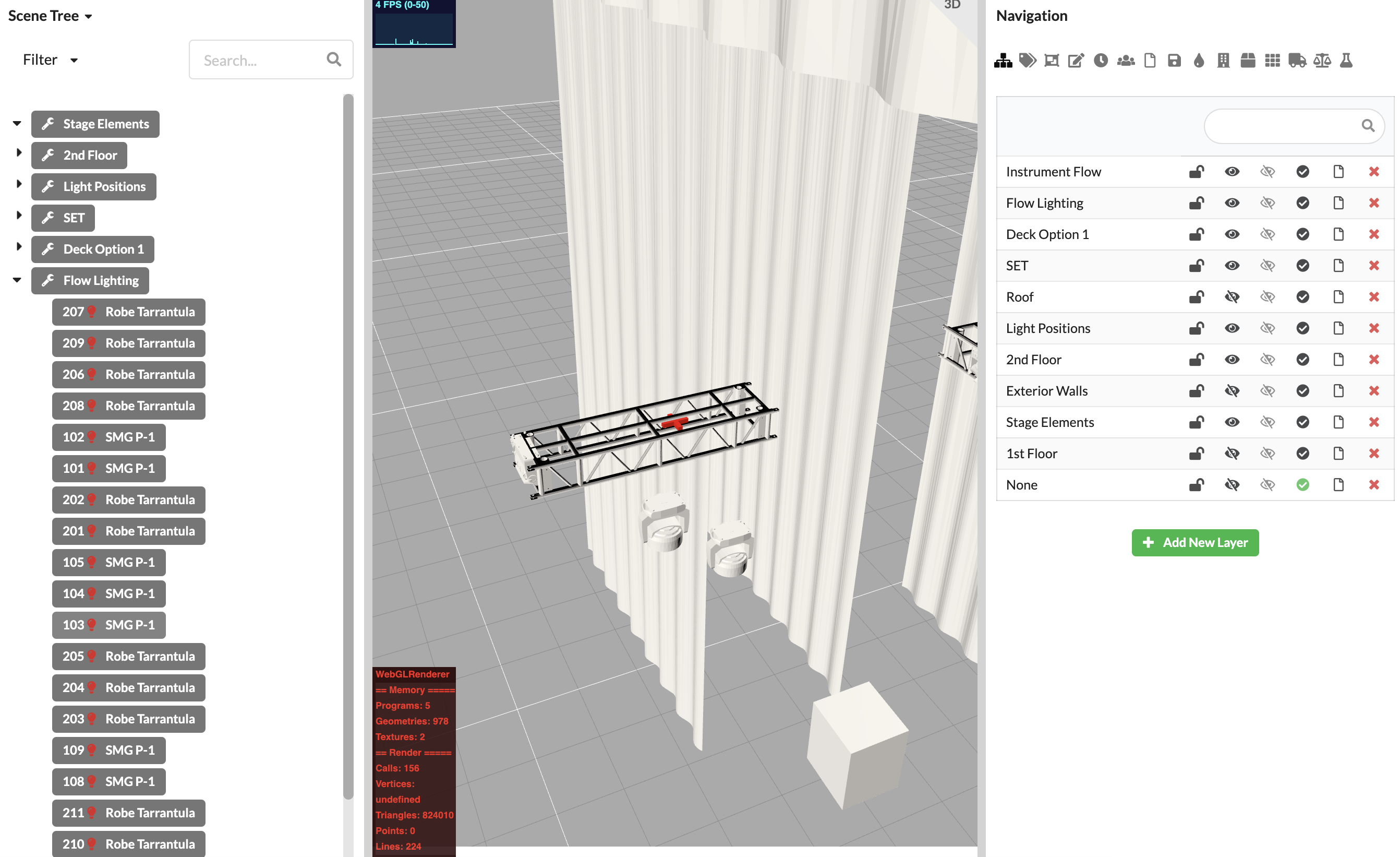
After importing, you will see all imported objects in the Scene Tree. You will also find an existing class and layer structure in the Navigation.
You can click individual objects in the Scene Tree or Renderer and their properties will be displayed in the Object Properties. You can also edit them there and also have the option of customizing the selection properties in the toolbar. For example, you can select all objects with the same name or use the box to activate several objects in one area.
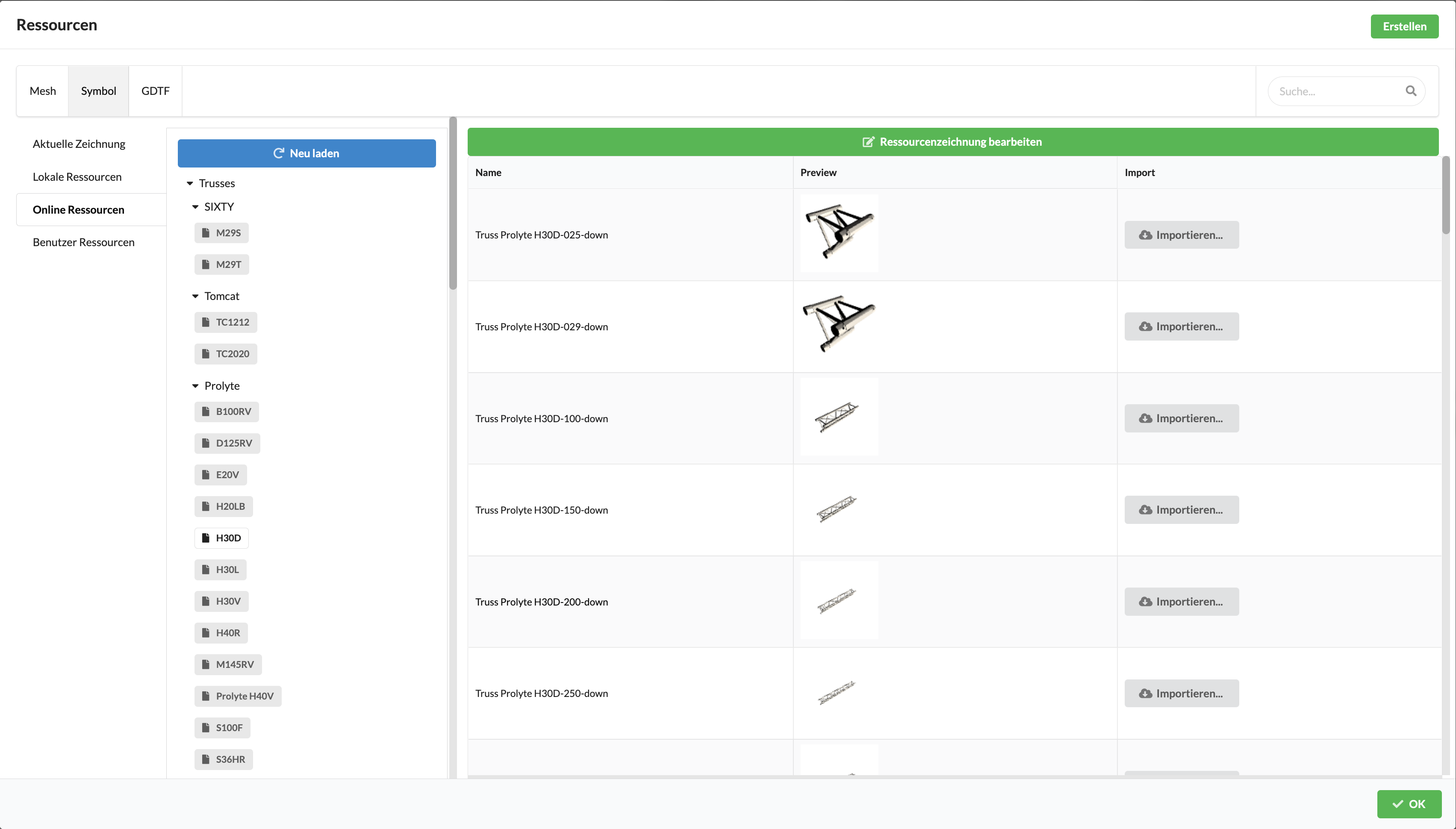
If you still want to replace imported symbols with symbols from the Production Assist Library after importing or in the course of your work, you can do so by right-clicking on the symbol and selecting the Change Defining Resource command. The resource selection opens.
On the left, you can select the source of the icons. Symbols can come from your open drawing (Open Documents), your locally stored library (Local Resources), or the Production Assist Library (Server Resources). Select the desired source and then click on the gray "Import" button to the right of the icon. If you want to import an icon from a source not listed here, click on the green "Import" button in the upper right corner and select the source file.
The Scene Tree displays all objects in your drawing and, if necessary, their common relationship, for example, which objects are located on the same traverse/light position. Currently, it is not possible to transfer structuring already made in drawings via MVR Exchange. That is why you have to restore them in order to be able to continue working productively with Production Assist. You create so-called Assembly Groups for grouping related objects.
If you have already defined a good structure along the lines of layers or classes, it can be very helpful to group all the objects in the Scene Tree first. To do this, click on Edit on the menu bar and then on Group by Class or Group by Layer.
You have now grouped objects that belong to the venue or set. If you now want to create individual trusses and their fixtures as an Assembly Group, you have several options:
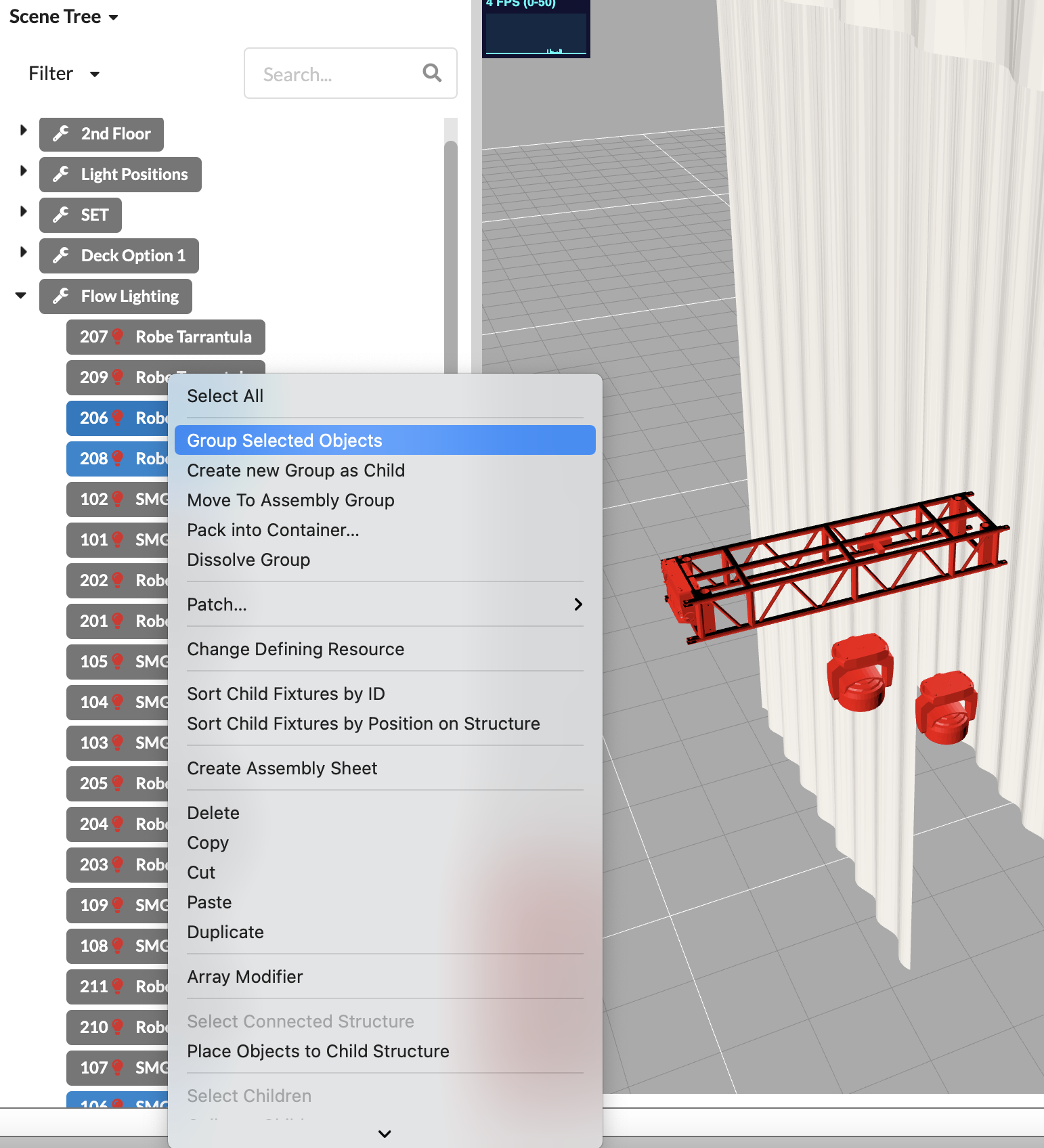
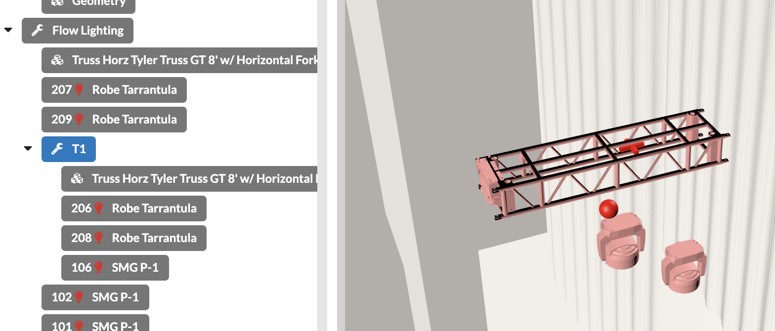
You click on the related objects in the Scene Tree and then right-click on the last object to select the command Group Selected Objects and enter the name you desire for the assembly.
While holding down the SHIFT key you can select several objects in a row, or while holding the CMD/CTRL key down, you can individually select several separate objects.
You click on the related objects in the Renderer and then right-click on the last object to select the command Group Selected Objects and enter the name you want for the Assembly Group.
While holding down the SHIFT key you can select several objects in a row, or while holding the CMD/CTRL key down, you can individually select several separate objects. Or you can use the selection variant Box in the toolbar.
Now you can create an Assembly Group for all your assemblies/areas and drag and drop them to arrange them in the Scene Tree or drag forgotten objects into it.
When creating Assembly Groups, it can also be very helpful to use the filter in the Scene Tree to display only certain object types. Or you can control the visibility of the objects via the existing layers and classes in the Navigation.
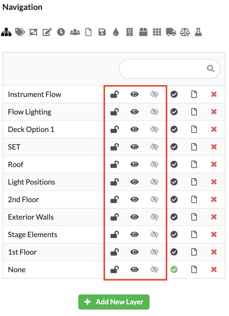
Use the lock icon to lock and unlock a layer or class. Objects on locked layers or classes cannot be selected and therefore not edited. However, they are still visible in the Scene Tree and in the Renderer. You use the black eye to control whether objects on this layer/class are visible or invisible. Invisible objects cannot be selected and are not displayed in the Scene Tree or Renderer. If you activate the gray eye for one or more layers/classes, only objects on this layer/in this class are visible. All other objects become invisible, regardless of the setting of their black eye.
If you have structured your Scene Tree well, you now have different options to continue working.
Create power and network patch documentation.