

The Navigation is located on the right side of the user interface. Here you manage the structure of your plan as well as many organizational areas such as classes, Layer, users, worksheets and static calculations.
If you're new to Production Assist, it's best to work your way through the registers from top to bottom. This way you first understand the plan structure and then the further areas.
If you are using the Navigation for the first time, this order will help you:
Tip for beginners: If you don't need a feature immediately, you can ignore it for now. For many workflows, Layer, Classes, Assembly Sheets and Saved Views are initially sufficient.
| Navigation | Name |
|---|---|
| 1 | Classes |
| 2 | Layers |
| 3 | Selection Groups |
| 4 | Print Labels |
| 5 | Presets |
| 6 | Time Lines |
| 7 | Users |
| 8 | Assembly Sheets |
| 9 | Tasks |
| 10 | Saved Views |
| 11 | Color Codes |
| 12 | Departments |
| 13 | Cases |
| 14 | Racks |
| 15 | Trucks |
| 16 | Errors |
| 17 | Load Groups |
| 18 | Load Combinations |
| 19 | Influence Lines |

Note about sorting and searching: By default, entries are sorted after they are created. In many tabs you can change the sorting using the symbol on the left in the header area. To the right of it you will usually find a search field that you can use to filter the list by name.
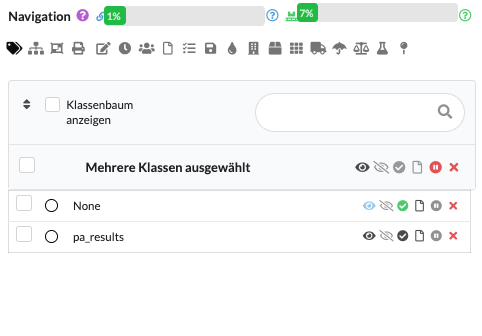
Classes are sublevels of layers. This allows you to structure objects more finely, for example by product type, model or function. Classes also control the visibility of objects: all elements in the same class can be shown or hidden together.
Use Classes if a single Layer is too coarse and you need further subdivisions within it.
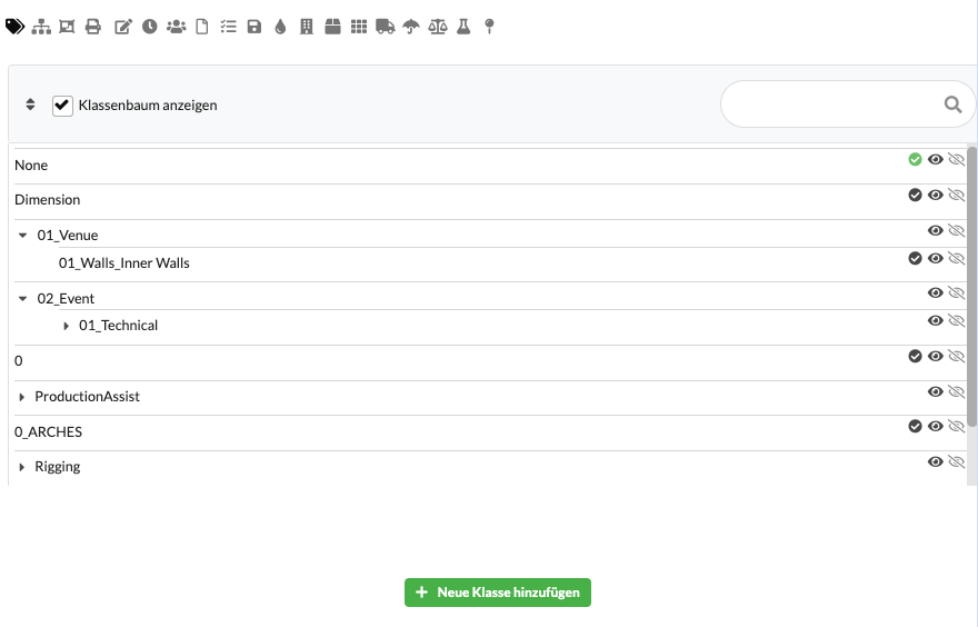
Use the green button Add New Class to create a new class. You can change the name directly in the Navigation.
Use the black eye to show or hide the objects of this class in the Renderer and Scene Tree. The gray eye only shows this class and hides other classes. This view is particularly helpful if you want to focus on a specific part of the plan.
The hook indicates which class is currently active. New objects are then automatically assigned to this class.
Use the paper symbol to quickly create an Assembly Sheet only for the objects of this class.
Use the cross symbol to delete the class.
If you activate Show class tree, child classes will be displayed as a tree structure. This means that the overview is retained even with many entries.
| field | Description |
|---|---|
| View Class Tree | Switches on the tree view so that nested classes are clearly displayed. |
| Name | Displays the name of the class. Clicking on the name allows renaming. |
| Visibility | The black eye shows or hides all objects of this class. |
| Only this class visible | The gray eye isolates the class so that other classes are hidden. |
| Active | The selection circle or tick marks the class as the active target class for newly inserted objects. |
| Create Assembly Sheet | The paper symbol directly creates an Assembly Sheet for the objects of this class. |
| Delete | The red cross removes the class from the project. |
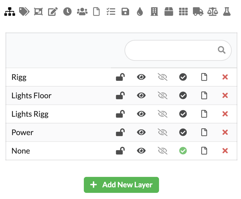
With Layers you structure the plan according to trades, areas or tasks. All objects on the same Layer can be shown or hidden together. Additionally, you can lock Layer so that they are not accidentally edited.
For most projects, Layer is the most important basic structure.
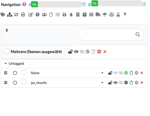
Use the green button Add New Layer to create a new Layer. You can change the name directly in the Navigation.
Use the lock symbol to lock or unlock a Layer. Objects on locked layers cannot be moved, selected, or edited.
Use the black eye to show or hide all objects of the Layers in the Renderer and in the Scene Tree. The gray eye only shows this Layer and hides other Layer. This is particularly practical if you want to specifically check individual areas.
The hook indicates which Layer is currently active. New objects are then automatically assigned to this Layer.
Use the paper symbol to quickly create an Assembly Sheet just for the objects of this Layer.
Use the cross symbol to delete the Layer.
| field | Description |
|---|---|
| Name | Displays the name of the Layers. Clicking on the name allows renaming. |
| Block | The lock symbol protects the Layer from accidental editing. |
| Visibility | The black eye shows or hides all objects of the Layers. |
| Only this layer visible | The gray eye isolates the Layer and hides other layers. |
| Active | The selection circle or tick marks the Layer as the target for newly inserted objects. |
| Create Assembly Sheet | The paper symbol creates an Assembly Sheet for all objects on that Layer. |
| Delete | The red cross deletes the Layer. |
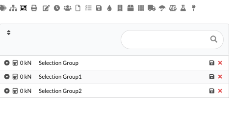
A Selection Group is a freely definable, reusable group of objects from the Scene Tree or the Renderer. It is used to quickly select identical sets of objects and to reuse these selections in workflows or evaluations.
Use the green button Add New Selection Group to create a new group. Select the desired objects in the Scene Tree or Renderer and save the selection with the floppy disk symbol. Alternatively, you can first create a new group and then adopt an existing selection. With the cross symbol you delete a group, the circle button activates all objects stored in the group.
Important: Aggregated calculation values can be displayed for each Selection Group (e.g. total load, reaction values or other result variables). The result value displayed summarizes these values from the included objects and helps you see at a glance how much load there is in the current selection. These evaluation values are displayed in the panel and can optionally be displayed as a label in the drawing area - practical for documentation and reports.
The Reset calculation button deletes saved calculation results for the selection so that you can start a new evaluation with current data.
| field | Description |
|---|---|
| Name | Displays the name of the Selection Group. Clicking on the name allows renaming. |
| Activate selection | The circle button in front of the name activates the objects saved in the group. |
| Result value | Displays aggregated calculation values (e.g. total load, reaction values) of the group; can also be visible as a label in the drawing area. |
| Save | The floppy disk icon saves the currently selected objects in the respective group. |
| Delete | The red cross removes the Selection Group. |
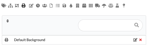
In the Print Labels area you manage all label layouts and print areas imported into the project. You can create new print areas, edit existing layouts and print labels individually or as a group. This area is particularly useful if you use labels as view areas: Then you can print a single label or an entire series directly from the view.
Use this area if you want to prepare labels for material, positions or transport.
| field | Description |
|---|---|
| Name | Displays the name of the print layout. |
| Edit | The pencil symbol opens the editing of the respective layout. |
| Delete | The red cross removes the print layout. |
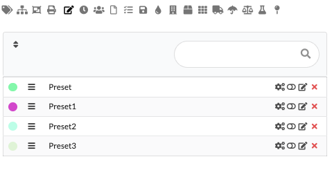
Presets save states of objects. These can be, for example, pan and tilt values, colors of spotlights or positions of trusses.
Presets are particularly helpful if you want to quickly recall recurring states.
Use the Add New Preset button to create a new Preset. You can change the name directly with a click.
The order of the Presets determines their priority. The top Preset has the highest priority, the bottom one has the lowest. You can use the three-bar symbol to change the order using drag&drop.
To edit a Preset, click on the gear icon next to the name. The Preset line is then highlighted in color. As long as the editing mode is active, changes in the Object Properties are saved in the Preset. Click the gear icon again to exit edit mode.
To activate a Preset, click on the switch until it turns green. The values stored in the Preset are then applied.
You can change the color of the Presets as well as the fade and delay times using the pen symbol.
To delete, click on the red cross.
Presets permanently save the changes made for this state and can be reused - even in calculations or in dynamically movable systems. This makes Presets particularly useful for testing different positions or configurations, running simulations reproducibly and quickly applying recurring processes.
| field | Description |
|---|---|
| Color | The color dot on the left helps to quickly distinguish Presets visually. |
| Order | The symbol with the three bars allows you to move using Drag&Drop and influences the priority. |
| Name | Displays the name of the Presets. Clicking on the name allows renaming. |
| Edit mode | The gear icon activates or exits the Presets's edit mode. |
| Activate | The switch displays the Preset or applies the stored values. |
| Properties | The pencil icon opens the settings for color as well as fade and delay times. |
| Delete | The red cross removes the Preset. |
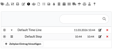
A Time Line consists of a sequence of steps (Steps). Each Step describes an action at a specific point in time. Use the Add TimeLine button to create a new Time Line. You can change the name directly.
| field | Description |
|---|---|
| Play | The play symbol starts the respective Time Line or the individual Step. |
| Expand | The arrow shows or hides the included steps. |
| Name | Shows the name of the Time Line or the Step. Clicking on the name allows renaming. |
| Timing | Shows the date, start time or times of the Time Line or the Step. |
| Edit | The pencil symbol opens the settings of the Time Line or the Step. |
| Delete | The red cross removes the Time Line or the Step. |
| Add schedule entry | Creates a new Step within the opened Time Line. |
You can add and name any number of steps to each Time Line using Add New Time Line Step. Use the bar symbol to change the order using drag&drop. Use the pen symbol to edit the step, and use the play symbol to play it directly.
To open the Preset selection of a Time Line, click on the pen icon in the corresponding line.
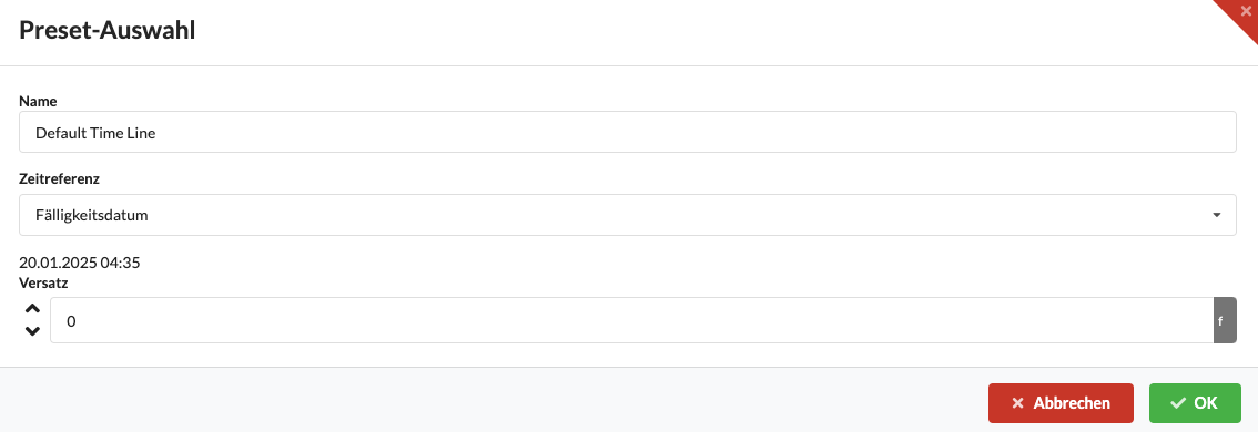
| field | Description |
|---|---|
| Name | Timeline name. You can change it freely. |
| Time reference | Specifies which date or reference point the timeline refers to. |
| offset | Moves the timeline relative to the selected time reference. |
| Cancel | Closes the window without saving. |
| OK | Saves the changes and closes the window. |
If you want to adjust a single step, open the Preset Selection Window using the pen symbol. There you determine what the Step is called, which Presets are switched on or off and whether there are dependencies on other Presets. You can also enter fade and delay times. These values are primarily intended for animations and time-controlled processes.
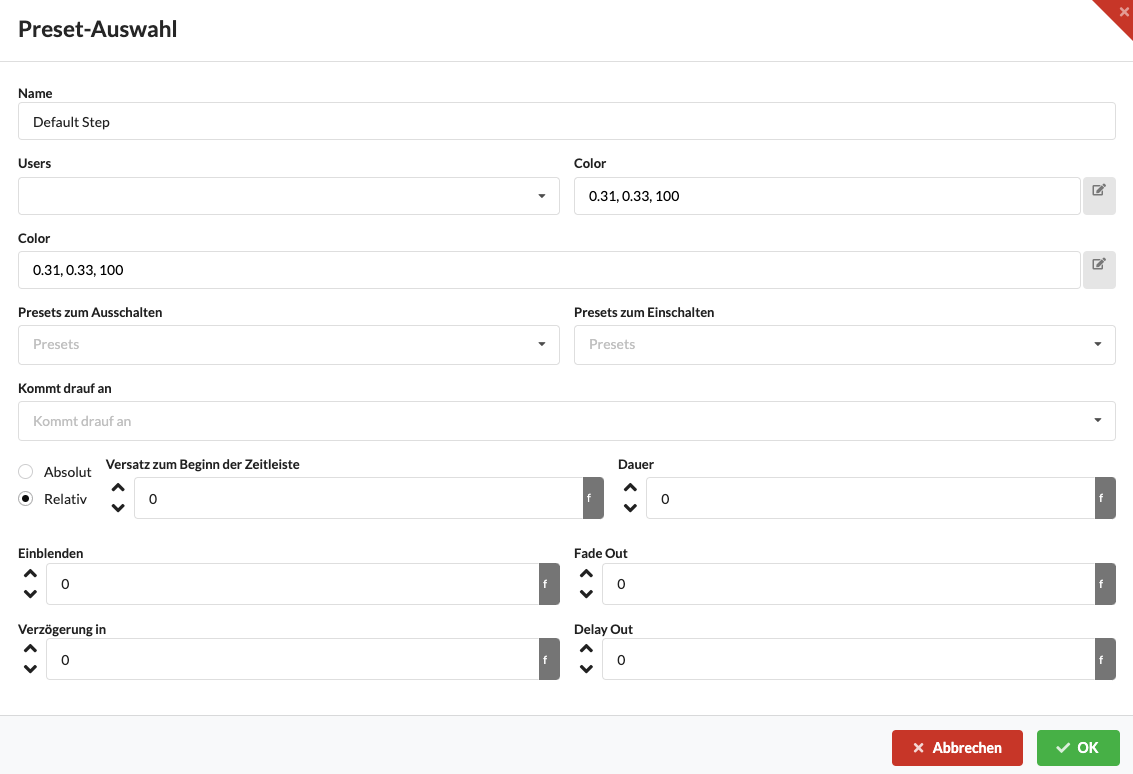
| field | Description |
|---|---|
| Name | Name of the step as it appears in the timeline. |
| Users | Assigns users or teams to the Step. |
| Color | Sets a color for better distinction. |
| Presets to turn off | These Presets are deactivated when executing the step. |
| Presets to power on | These Presets are activated when executing the step. |
| Dependencies | The Step only starts when the stored conditions are met. |
| Absolute/Relative | Determines whether the time is absolute or relative. |
| Offset to start of timeline | Moves the Step within the timeline. |
| Duration | Determines how long the Step is active. |
| Show | Duration of display. |
| Fade Out | Duration of hiding. |
| Delay in | Waiting time before the start of the step. |
| Delay Out | Waiting time after the end of the step. |
| OK | Saves the changes and closes the window. |
| Cancel | Closes the window without saving. |
In order for you to be able to add people to the plan in the Users tab, the project must be saved online on the Production Assist platform. The users are first assigned to the project there and then added to the plan via Add New User.
Created users can then be assigned to, for example, Assembly Sheets or other organizational areas.
If your project remains purely local, you usually don't need this area.
You can find further information about the online workflow in the chapter Online Workflow.
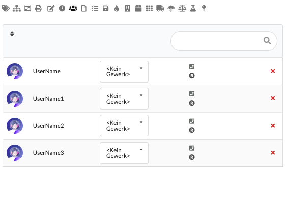
| field | Description |
|---|---|
| User | Displays the avatar and name of the person involved in the project. |
| trade | The dropdown is used to determine which trade the user is assigned to. |
| Releases | The icons on the right show project-related rights or status information of the user. |
| role | The role symbol indicates the stored role in the project context. |
| Delete | The red cross removes the user from the plan's list. |
Assembly Sheets help you to divide the paperwork into useful assemblies. This allows you to view, edit or print specific groups of objects separately. For example, you can create a separate worksheet for each truss line. In Worksheet Window you will only see the matching objects. Users and Timeline Steps can also be assigned to an Assembly Sheet, for example for responsibilities and scheduling.
This area is particularly useful when several people are working on structure, documentation or print documents.
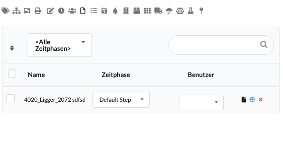
| field | Description |
|---|---|
| Time phase filter | Filters the list according to the selected time phase. |
| Search | Searches the existing Assembly Sheets by name. |
| Name | Displays the name of the Assembly Sheets. |
| time phase | Assigns the worksheet to a time phase. |
| User | Assigns a responsible user to the worksheet. |
| Open worksheet | The document icon opens the associated worksheet in the app. |
| Open online task | The globe icon opens the associated task on the website. |
| Delete | The red cross removes the Assembly Sheet. |
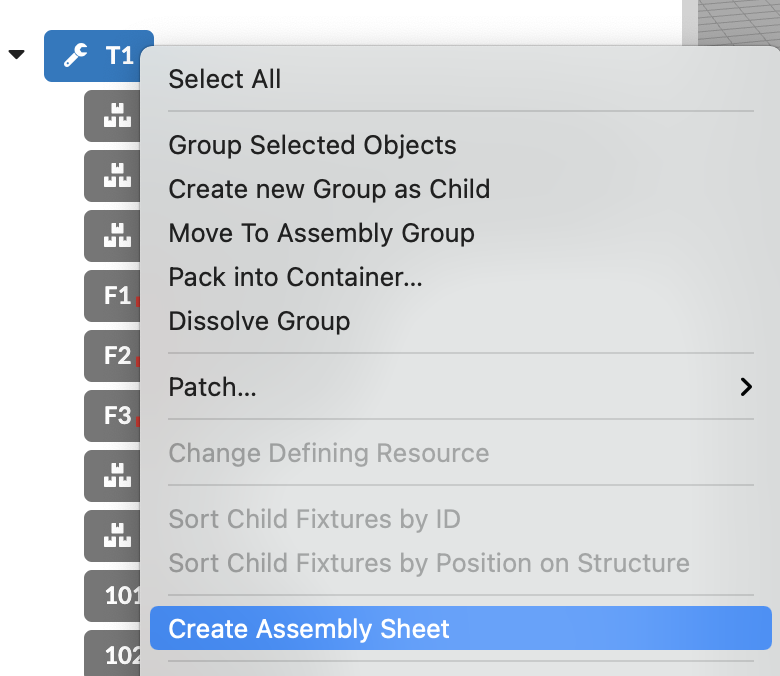
There are several ways to create Assembly Sheets:
There is currently no detailed description available for Tasks.
If you work in this area, use it initially in addition to Assembly Sheets and the online task view until the complete documentation has been added.
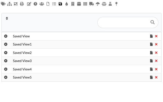
With Saved Views you save specific views of the plan (2D or 3D) including image detail, visibility and active elements. This is useful if you regularly need the same perspectives for paperwork, reconciliations or exports.
This is how it works: Set the desired view and click on Add Saved View. The name and preview can then be adjusted. You can call up the saved view using the button in front of the entry; The black paper symbol overwrites the view with the current image section. With the red cross symbol you delete a Saved View, the copy symbol duplicates it.
Important: Saved Views are primarily relevant for the desktop app because they address the desktop Renderer. When exporting (PDF/Report), you can specifically use a saved view — there is a Markdown syntax in the report templates that can be used to call a specific Saved View when creating the PDF. Plugins can provide their own views; Whether and how these can be used in reports is stated in the respective plugin/report documents.
Note: When sharing projects or working in the cloud, depending on how they are stored, locally created Saved Views may not be automatically available in other environments. In such cases, check the project sync settings or export the view into a report template.
| field | Description |
|---|---|
| Call view | The circle button in front of the name restores the saved view. |
| Name | Displays the name of the saved view. Clicking on the name allows renaming. |
| Update | The black paper symbol overwrites the saved view with the current status. |
| Delete | The red cross removes the Saved View. |
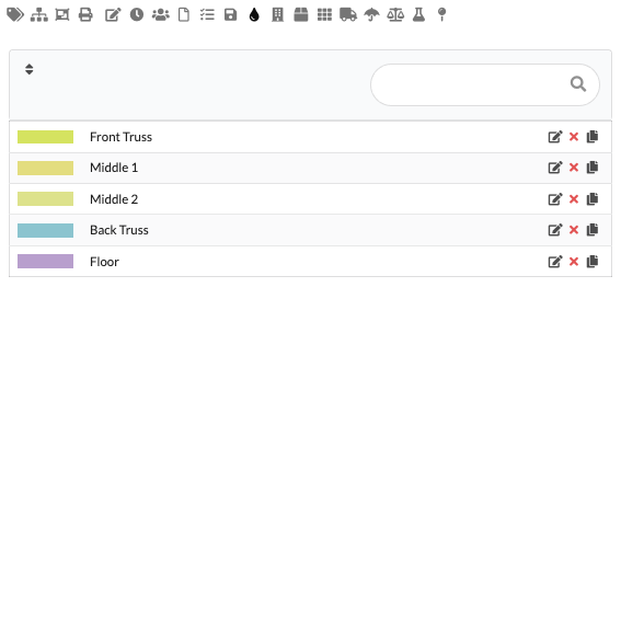
You can assign a Color Code to any object in the drawing. A Color Code can contain a single color, multiple colors, or a gradient. Color Codes are used to visually mark objects and assign them more quickly - both in the Renderer (2D and 3D) as well as in the paperwork/worksheet and in the PDF export. In tables or PDF printouts, the colors appear as markers; Labels on objects can also adopt the Color Codes.
Use Add New Color Code to create a new color code and name it directly in the list. You can change the color(s) using the pen symbol. With the red cross you delete the entry. The copy symbol quickly creates a similar variant.
| field | Description |
|---|---|
| Color | The colored area on the left shows the currently set color code. |
| Name | Displays the name of the color code. Clicking on the name allows renaming. |
| Edit | The pencil symbol opens the editing of the color code. |
| Delete | The red cross removes the color code. |
| Duplicate | The copy symbol creates a copy of the color code. |
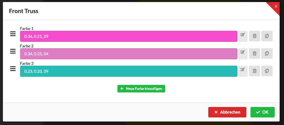
The image shows the editing mode for Color Codes. Here you can add multiple colors, set the order and transitions (gradients), and see a preview. Color gradients are displayed as a gradient in the list. Use multiple colors, for example for labels (e.g. ground colors: red → green) or yellow-green gradations to visually distinguish states or categories. The set Color Codes are adopted in the Renderer, in labels and in the PDF export.
In the Edit mode, there are small handles on each color line - usually shown as three bars - with which you can move the order of the colors using drag & drop. You can see a preview of the currently selected color using the indicator button next to the color; Clicking on it opens the color picker, which you can use to change the color. The delete symbol removes the respective color from the Color Code, the copy/duplicate symbol creates an exact copy of the color in the same color palette. Changes are immediately displayed in the preview and apply to Renderer, labels and PDF exports.
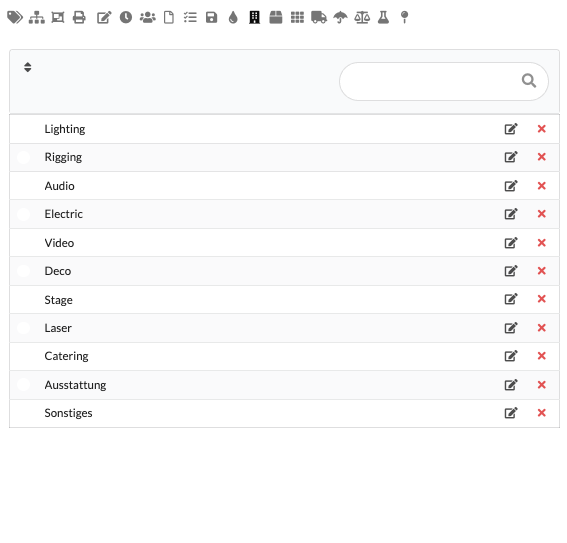
In the Departments area you manage all the trades involved. You can use this assignment later in the paperwork or in lists, for example for power connections or responsibilities.
So it remains clear which trade is responsible for which area.
Use Add New Department to create a new trade. You change the name directly in the list. With the red cross you delete the entry again.
| field | Description |
|---|---|
| Name | Displays the name of the trade. Clicking on the name allows renaming. |
| Edit | The pencil symbol opens editing the entry. |
| Delete | The red cross removes the trade from the list. |
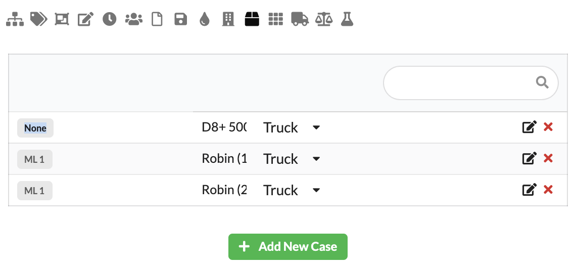
For truck planning, you can combine objects such as spotlights or video elements in Cases. This will help you keep track of what needs to be transported together. The templates for different Case sizes are created in Resource Manager. In the Navigation you create the required Cases for your project.
A Case is useful if several objects are always stored or transported together.
Use Add New Case to select a template and specify how many Cases should be created. To the left of the name you can see which template was used. You can change the name directly. You can also choose which Truck the Case should be loaded into. Use the red cross symbol to delete the Case.
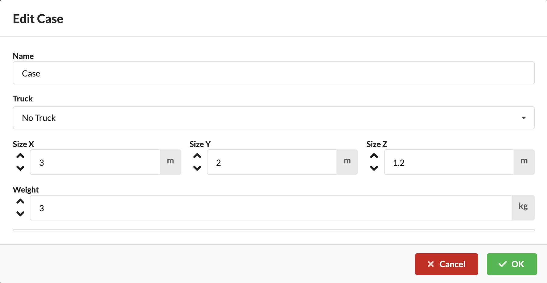
Use the pen symbol to open the Edit Case Window. There you change the name, size and Truck assignment of the Cases.
| field | Description |
|---|---|
| Template | Displays the Case template used. |
| Name | Sets the name of the Cases. |
| Truck | Assigns the Case to a Truck. |
| Size | Determines the dimensions or capacity of the Cases. |
| Save | Applies the changes. |
| Cancel | Closes the window without saving. |
How to add objects to Cases can be found in the chapter Object Properties.
In Production Assist you can also plan Racks with devices from your drawing. This makes it possible to record which devices are installed or transported together in a Rack. The templates for different rack sizes are created in Resource Manager.
A Rack is particularly helpful if you want to manage devices as a fixed technical unit.
Use Add New Rack to select a rack template and create a new Rack. You can later adjust the size and weight using the pen symbol.
| field | Description |
|---|---|
| Template | Displays the Rack template used. |
| Name | Sets the name of the Racks. |
| Size | Determines the Rack size. |
| Weight | Stores the weight of the Racks. |
| Save | Applies the changes. |
| Cancel | Closes the window without saving. |
To the left of the name you can see which template was used for the Rack. You can change the name directly. Use the red cross symbol to delete the Rack.
How to add objects to Racks can be found in the chapter Object Properties.
All objects in the drawing can be assigned to a Truck directly or via Cases. This way you can see more quickly how many Trucks are needed and which elements should be loaded where. The templates for different truck sizes are created in Resource Manager. In the Navigation you create the required Trucks for your project.
This area is particularly useful for transport planning and logistics.
Use Add New Truck to select a truck template and enter information about loading and the logistics company. You can change or add this information later using the pen symbol.
| field | Description |
|---|---|
| Template | Displays the Truck template used. |
| Name | Sets the name of the Trucks. |
| Logistics company | Stores the associated shipping company or company. |
| Loading information | Stores additional loading information. |
| Save | Applies the changes. |
| Cancel | Closes the window without saving. |
To the left of the name you can see which template was used for the Truck. You can change the name directly. Use the red cross symbol to delete the Truck.
How to assign objects directly to Trucks can be found in the chapter Object Properties.
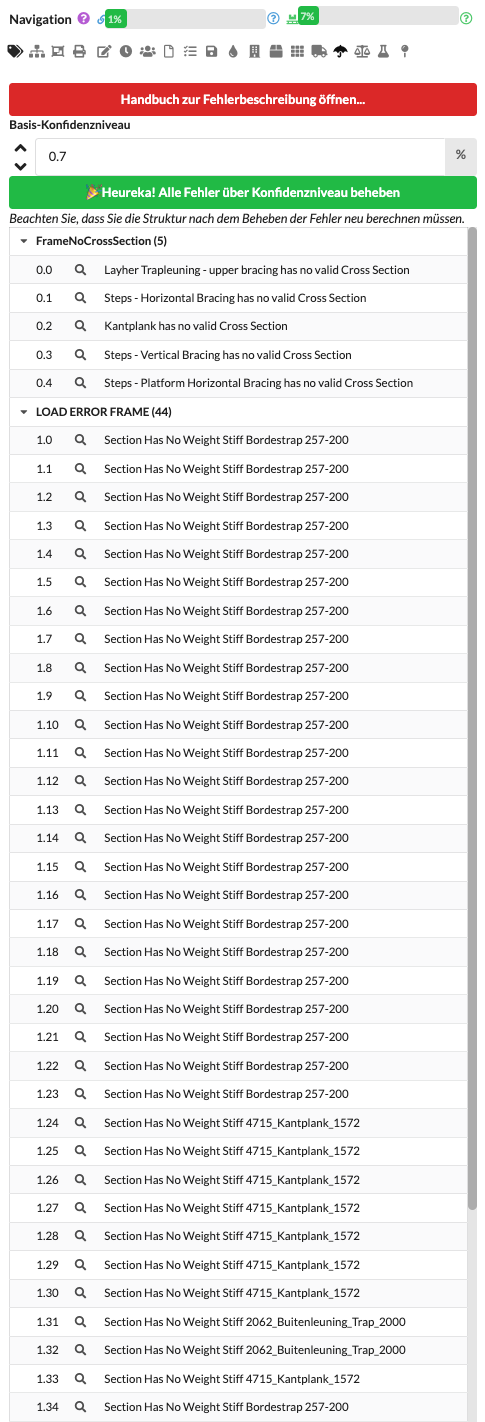
In the Errors area you will find an overview of problems, warnings and notes from the static system.
This area helps you to specifically find errors and correct them before a new calculation. It's best to work through the messages from top to bottom.
If messages continue to appear after correcting errors, restart the calculation to update the list.
Production Assist communicates errors primarily object-related: Each error message is assigned to a specific object and a specific position. You can show or hide these notifications in the quick properties so that only the notifications that are relevant to you remain visible. Plugins often store error messages on specific layers so that you can display, filter and process them specifically.
Many entries can be fixed using the Auto Fix workflow. Double-clicking an error in the list applies the suggested fix to the affected object. Changes can be undone at any time with Ctrl+Z (Windows) or Cmd+Z (macOS). The list of errors can be very extensive; So work through it step by step (little by little).
The Auto Fix workflow can be configured to automatically fix all errors above a configurable confidence level. The confidence level indicates how certain the algorithm is that a proposed fix is correct. A typical example is the assignment of a load to a structural element: If it is unclear which of several possible elements is suitable, the reliability of the automatic assignment is reduced. You can adjust the confidence level, run automatic fixes, or confirm individual fixes manually — and undo any steps if necessary.
| field | Description |
|---|---|
| Open error description manual | Opens the error manual with a reference to the respective entry. It explains what the message means and what steps are recommended to resolve it. |
| Base confidence level | Specifies the threshold at which messages are highlighted in the list. |
| Status notice | The green message indicates whether all errors above the selected confidence level have currently been corrected. |
| Error group | Groups similar messages, for example by error type. |
| Error entry | Displays a single warning or error. |
| Locate errors | The magnifying glass symbol jumps to the affected area or helps find the problem. |
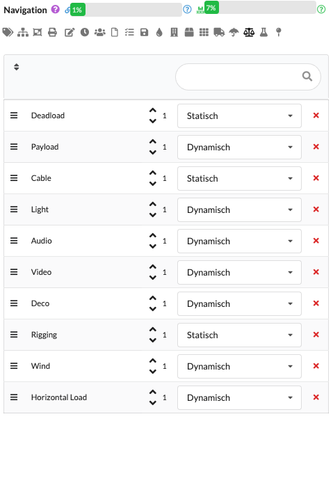
To enable static calculations, objects are grouped into load groups (Load Groups). A load group defines which load types (e.g. dead weight, payload, cable, light, audio, video, decoration, wind, horizontal loads) are applied to the included objects and how these are evaluated in later load combinations.
Procedure and benefits:
Special features for wind and horizontal loads:
Organization recommendation:
| field | Description |
|---|---|
| Name | Name of the load group, for example Deadload, Wind or Light. |
| factor | Safety or additional factor by which the loads of this group are multiplied. Optionally, you can enter an additional, user-defined factor here that is automatically applied to all load cases in this group (e.g. to take uncertainties or different load assumptions into account). Typically not required, but useful for special cases. |
| Type | Primarily informative: determines whether the load is described statically or dynamically. This value is used for categorization and representation and usually has no direct influence on the calculation routines. |
| Delete | Removes the load group from the list. |
How to add objects to Load Groups can be found in the chapter Object Properties.
After creating the Load Groups you can calculate it in different Load Combinations. This way you can check different load cases, for example for usage, wind or limit states.
This allows you to compare different calculation scenarios separately without having to create the load groups every time.
For beginners it often makes sense to initially only work with a simple standard combination.
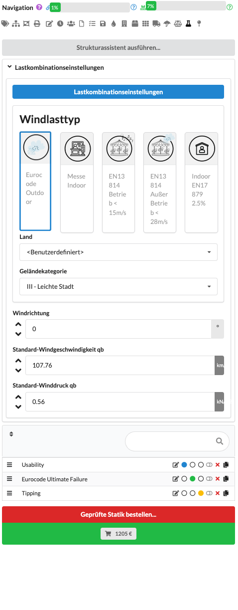
Three load combination types are available as standard, each used with different safety factors for specified verifications:
The combinations are color coded (blue, green, yellow). You can activate the colored dots to select the respective load case combination as the active basis; the system then uses the associated load cases and safety factors. Important: If when creating a load combination it is defined as a draft/design level, the system automatically sets the typical Eurocode safety factors (e.g. 1.35 and 1.5) for the corresponding verifications. In addition to the standard load cases, the checkboxes have an additional activation box ("Enable") with which non-standard load cases can be switched on. If this is activated, additional calculations run in the background so that several load case combinations can be checked at the same time for proof. You specify the load combination type in the load combination settings.
| field | Description |
|---|---|
| Load combination settings | Opens the detailed settings of the selected load combination. |
| Wind load type | Specifies the standard or application according to which the wind load is calculated. This determines which load assumptions and which verification approach are used for the wind calculation. |
| Country | Specifies the country or the associated set of regulations according to which the wind load calculation is carried out. This determines which national or regional specifications apply to wind zones, reference values and other wind parameters. |
| Terrain Category | Describes the structure's surroundings, such as open terrain or dense development. This classification influences how strong the wind is at the location. |
| Wind direction | Indicates from which direction the wind hits the structure. This determines the primary angle of attack for the calculation. For a reliable assessment, it can make sense to compare several wind directions. |
| Standard wind pressure qb | Displays the calculated reference wind pressure, which is determined based on the applicable standards and site parameters. It is a central input variable for the wind load calculation. |
| Standard wind speed qb | Shows the reference wind speed used, which is also derived from the local normative specifications. Wind speed and wind pressure have a direct quadratic relationship. |
| Combinations list | Lists all existing load combinations with status and editing options. |
| Structure status | Marks the load combination that is currently used for trusses or structures. This is shown by the green dot. |
| Motor/Bearing Status | Marks the load combination that is currently used for motors or supports. This is shown by the orange dot. |
| Edit | Opens the editing of the respective load combination. |
| Delete | Removes the load combination from the list. |
| Order verifiable statics | Starts the ordering process for tested statics if calculation and verification are to be checked and documented externally. |
| Price | Shows the current price of the order and usually opens the order overview for the checked statics together with the button. |
After you have created a load combination, you can change its name by clicking and activate it using the green dot. Use the pen symbol to edit the settings and use the red cross symbol to delete the combination.
Use the Add New Load Combination button to add a new load combination. In Edit Load Combination Window you specify general calculation values for dynamics or Eurocode tests. If you enter the value 0 for a load group, it will not be taken into account in this combination.
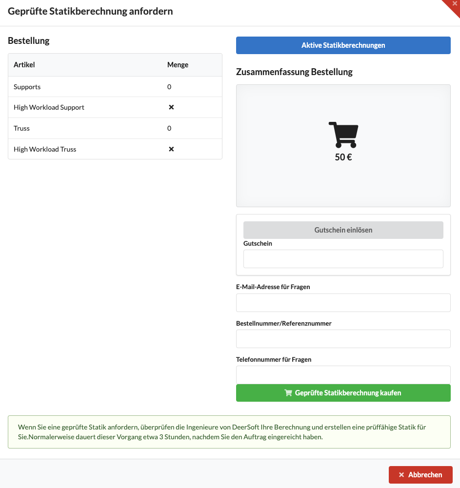
Use the red button Order tested statics... or the green price button to open the overview for ordering the statics calculation.
| field | Description |
|---|---|
| Order | Shows an overview of all items that are included in the statics calculation (articles, quantities, calculation scope). The structural design is based, among other things, on the number of supports and the number of cross-sections to be verified; Cross sections subject to heavy loads can be given a small percentage surcharge. The overview also shows how individual items affect the price and scope of the inspection. |
| Active structural calculations | Opens the list of all static calculations (in progress and completed) — the same view as on the Production Assist website. Shows the current processing status and allows you to download the structural documents to check whether the calculation has been submitted completely and correctly. |
| Redeem voucher | Enables entering a coupon code to apply discounts or clearances to the order. |
| Voucher | Field for a voucher code that can affect the total price of the order. |
| Order number/reference number | Field for information that should appear on the invoice or order summary (e.g. PO number, invoice number or internal reference). Makes allocation, billing and tracking easier. |
| Email address for questions | Contact address for written queries and for delivery of structural documents. We also recommend that you provide a mobile number so that we can reach you quickly via text message or call if necessary. |
| Telephone number for questions | Mobile or landline number for telephone inquiries; A mobile number (SMS/call) is recommended. For urgent questions or to deliver the structural documents at short notice, we primarily use this number. |
| Buy verifiable statics calculation | Complete the order and commission the verified statics calculation. |
| Cancel | Closes the window without ordering. |
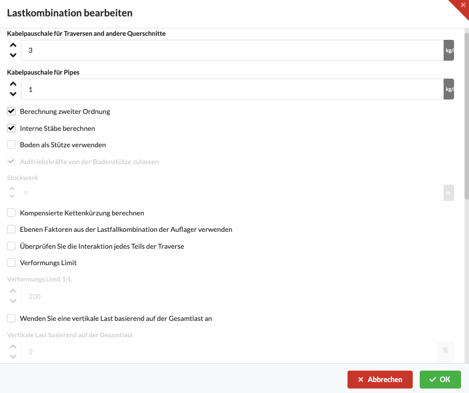
By clicking on Load combination settings you open the window for detailed editing of the load combination.
| field | Description |
|---|---|
| Cable flat rate for trusses and other cross sections | Enter a general cable weight per unit length here, which is also taken into account for trusses and similar cross sections. The flat rate serves as a practical approximation if you do not want to model individual cable positions - this way you systematically avoid cable weights that are too low. |
| Cable flat rate for pipes | Like the truss flat rate, but typically a slightly lower standard value for pipes, as in practice they hold fewer cables per meter. Use this value as a rough approximation if individual cables are not recorded in detail. |
| Second order calculation | Performs a non-linear (second-order theory) calculation: Deformations are iteratively fed back into the equilibrium calculation so that large deflections influence the effective internal forces. Activate this option for slender elements that are prone to buckling or if large deformations are expected. If the option is deactivated, the standard (first-order) analysis is calculated, in which deformations have no influence on the forces. If the second-order theory does not converge, it can be switched off to analyze with the first-order and identify stability or boundary condition problems. |
| Calculate internal members | Switches between the simplified replacement bar calculation and the detailed calculation of each individual bracing and chord tube. In order for the detailed calculation to work, truss symbols must be prepared: Create bracing and tube elements in the symbols and mark them as the “Internal Bar” type. This option takes local effects into account (e.g. at corners) and is particularly useful in ground support scenarios when local stresses are relevant. |
| Use floor as bearing | Allows the floor to be used as a bearing for automatic floor loading: Instead of manually inserting individual blue support bearings or gray support attachments, bearings are automatically positioned at the set bearing height on all structural elements that intersect that plane. Optionally, these bearings can be connected to the floor (e.g. screwed or ballasted) in such a way that lifting forces are absorbed and tipping is prevented. It is advisable to first calculate the ballast requirement and only then activate the connection. Individual objects retain their own settings as to whether their supports absorb uplift forces. |
| Allow lifting force on the ground | Allows ground supports to absorb lifting (upward) forces. If the option is active, the ground forces are connected to the ground (e.g. bolted or ballasted) in such a way that the structure cannot tip over. It is advisable to first use this option and calculate the required ballast before activating the connection. Note: Each object has its own setting as to whether a support can absorb uplift forces; the behavior may differ in non-linear calculations. |
| Calculate compensated chain shortening | Allows the drop effect in interlocking chain systems to be compensated: After each lifting process, the compensation ensures that traverses have no deflection at their supports and are leveled. This compensates for the typical support forces, which depend on the respective chain deformation in statically indeterminate systems. Activate the option if you want to level the systems; This option may be unsuitable for systems that cannot be leveled (e.g. ropes). Global activation can be deactivated again for individual ropes/objects. |
| Use level factors from the load case combination of the supports | If this option is active, the level factors are not taken from the selected load combination such as usability, Eurocode or tipping, but always from the load combination of the supports. This means that you only have to set these factors once in the blue load combination for the supports and not in each individual load combination. |
| Check interaction of each truss part | Checks the interaction at all calculation points of a traverse and not just at the actual connection points. The background to this is that in the area of real connectors, bending moment and shear force primarily influence the load-bearing capacity and the full effect of the bracing elements cannot always be taken into account in the design. If the option is activated, Production Assist treats each calculation point along the traverse as if there were a connector there. This allows the traverse to be valued conservatively along its entire length, regardless of its actual segmentation. |
| Deformation limit | Sets the general allowable deformation limit for the entire drawing or for all relevant trusses and structural elements. This global limit value is used when no more specific setting is relevant and thus forms the basis for the general assessment of usability. |
| Deformation limit 1/L | Sets the global deformation limit relative to the part length, for example as L/200 or L/300. The permissible deflection is therefore not assessed in absolute terms, but always in relation to the relevant length. If level-specific deformation limits are also defined, the actually relevant limit value is always decisive. |
| Apply horizontal equivalent load from total load | Activates an additional horizontal equivalent load, which is derived as a percentage of the total load or dead load of the system. The size of this equivalent load is determined via the associated percentage value. This is particularly helpful for platforms or similar structures when, in addition to the usual loads, additional substitute loads have to be taken into account. |
| field | Description |
|---|---|
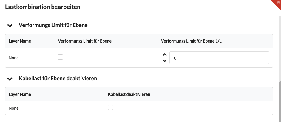
| Deformation limit for plane | Defines a custom deformation limit per layer. This means that individual levels can be specifically evaluated differently than the entire system, for example a pre-rig compared to the main grid. This is particularly useful if different levels have to be assessed differently depending on their function or normative requirements. |
| Layer Name | Displays the names of existing layers for which custom deformation limits can be defined. This makes it clear which level a different specification applies to and where there is a deliberate deviation from global standard values. |
| Deformation limit for plane 1/L | Sets the allowable deformation limit of a plane relative to its governing length. Production Assist automatically determines the system length and actual deflection, compares both with the limit value, for example L/200, and reports any excesses as impermissible deformation. |
| Disable cable load for layer | Excludes the cable load for individual levels from the calculation. This is helpful if certain levels are not intended to accommodate cable loads or are deliberately excluded from this in the configuration under consideration. |
| field | Description |
|---|---|
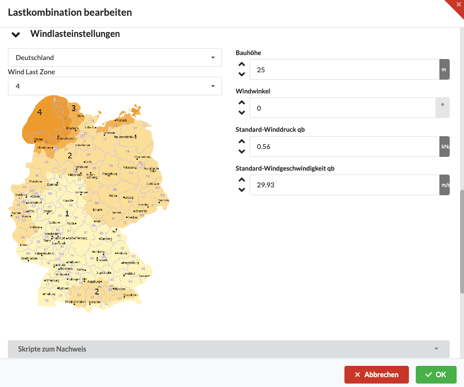
| Wind load settings | Contains the parameters for calculating the wind load. |
| Country | Specifies the country or the applicable regulations. This sets the national or regional specifications for wind zones, reference wind speeds, wind pressures, terrain categories and other standard-dependent parameters. If a required country is not available, this should be reported to Production Support. |
| Wind load zone | Determines the regional wind load zone from which the relevant reference values for wind pressure or wind speed are derived. Depending on the regulations, this is done via zones such as 1 to 4 or directly via reference values such as 25 m/s. The selection has a direct influence on the entire wind calculation. |
| Overall height | Indicates the total height of the structure above the ground. The display primarily serves to provide information and comprehensibility in the interface; Production Assist uses the actually relevant heights of the individual elements for the calculation. |
| Wind angle | Specifies the angle at which the wind hits the structure. By default, the wind calculation is initially performed for a single direction; the set value defines the primary angle of attack. For reliable results, it can make sense to compare several directions or to carry out the calculation for all wind directions. |
| Standard wind pressure qb | Displays the calculated reference wind pressure, which is determined based on the applicable standards and site parameters. It is a central input variable for the wind load calculation. |
| Standard wind speed qb | Shows the reference wind speed used, which is also derived from the local normative specifications. Wind speed and wind pressure have a direct quadratic relationship. |
| Scripts for proof | Executes JavaScript scripts stored in the Arena version for additional checks and verification. This allows project or system-specific rules to be evaluated that are not directly covered by normal static calculations, for example special requirements for ceiling structures, numbers of loads in defined radii or permissible load situations in certain areas. The results can then be displayed in the drawing and used for further evaluation. |
The load combinations Eurocode9 for trusses and Usability for motors are usually available as standard. You can assign different load combinations to trusses and motors. The orange dot stands for motors or supports, the green dot for trusses or structures.
If you are unsure, start with the standard values and only adjust individual parameters.
Suitable load combinations are already stored in many projects, for example for trusses according to Eurocode9 and for motors or supports according to Usability. Production Assist typically distinguishes between serviceability for deformation verification and ultimate limit state for load-bearing capacity verification. As a rule, no safety factors are used for proof of suitability for use, while the relevant safety factors are taken into account for proof of ultimate load capacity. Depending on the system used, Production Assist automatically selects the appropriate approach, for example according to ASCE, older DIN aluminum regulations or the current Eurocodes.
You can find a tutorial on static calculations here.
In the area Influence Lines you analyze displacements, rotations and forces on cross sections. This allows you to specifically assess the behavior and load distribution of the structure.
It's best to start with a single display, for example load or deflection, and only show other values if necessary. If the display becomes confusing, first reduce the number of displayed results and only increase the scaling in a targeted manner.
All results in this area come from the object Production Assist Calculation Results. If results are missing, first check whether its class or level is visible. If the display still remains incomplete, it may help to delete this object; it will be automatically regenerated during the next real-time calculation.
| field | Description |
|---|---|
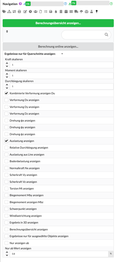
| View calculation overview online | Opens the current calculation overview in a separate online view in the browser. After each calculation, Production Assist transfers the associated calculation data to the Production Assist server. There, calculation results and metadata such as loads, settings and boundary conditions can be transparently viewed, documented and passed on to third parties. |
| Show results for cross sections only | Restricts the display of results to a specific cross-section type. The cross sections used in the model can be selected from the drop-down menu. This means that only the cutting reactions, utilization and other results of this type can be specifically analyzed, while other cross-sections remain hidden. |
| Scale force | Adjusts the display size of the displayed forces. The physical result is not changed, only the graphical scaling so that forces in the drawing remain more legible and comparable. The entry acts as an additional manual adjustment to the display scale that has already been automatically calculated. |
| Scale moment | Adjusts the display size of the displayed moments. In this way, torque curves can be highlighted more clearly if necessary without changing the underlying calculation results. As with the forces, only the representation is changed, not the calculation result. |
| Scale deflection | Adjusts the display size of the deflection shown. This is helpful if you want to make deformations in the model more visible or more legible in dense surroundings. Here too, only the graphical representation is adjusted. |
| Show combined deformation | Displays the resulting total deformation of the cross section. This value corresponds to the combined deformation Du and results from the vectorial superposition of the individual deformation components. |
| Show deformation Dx | Shows the displacement of the system in the X direction. This makes it possible to specifically assess how much a structural element or overall system deforms in this axis under load. |
| Show deformation Dy | Shows the displacement of the system in the Y direction. This makes it clear whether and to what extent the system shifts in this direction under load. |
| Show deformation Dz | Shows the displacement of the system in the Z direction. Together with Dx and Dy, this value forms the basis for assessing the overall deformation. |
| Show rotation φx | Displays the rotation of the system around the X axis. This makes it possible to assess whether components or the entire system twists relevantly around this axis. |
| Show rotation φy | Displays the rotation of the system around the Y axis. This is helpful if rotations in this direction are relevant for assessing the deformation behavior. |
| Show rotation φz | Displays the rotation of the system around the Z axis. This makes it possible to check whether and where the system twists in the plane or around the vertical axis. |
| Show utilization | Shows the utilization of the cross-section as a proportion of its permissible load capacity. A value of 100% means that the permissible stress has been reached; higher values indicate overload. The relevant utilization of the element is displayed, for example for trusses, PE beams or other statically evaluated profiles. For a detailed analysis, you can use the calculation overview to see which internal forces or load combinations cause this utilization. |
| Show relative deflection | Compares the actual calculated deflection with the permissible limit value of the respective cross-section or design. Typical limit values are, for example, L/200; Depending on the system, load combinations, standard specifications or stored manufacturer data are used as a basis for comparison. A meaningful comparison is only possible if a corresponding deflection analysis is activated and defined. The limit values can be set in the load combinations; For US trusses, already stored manufacturer data is often used. Results marked in red indicate that the permissible deflection has been exceeded. |
| Show utilization as a line | Displays the utilization along an element as a line instead of as a color gradient. The red line marks the reference value of 1.0 or 100%, an additional white line shows the actual utilization at the individual points of the element in relation to this. This often makes it easier to identify local peaks, differences between values that are close together and critical areas. |
| Show soil loading | Shows the distributed surface load acting on the ground. What is meant is the average load on a surrounding surface and not the local pressure at a single contact point. |
| Show normal force Nx | Displays the normal force Nx along the longitudinal axis of the structural element in the local element system. This makes it clear which tensile or compressive force is acting in the longitudinal direction of the element. |
| Show shear force Vy | Displays the shear force Vy in the local element system. The value describes the shear force in the Y direction based on the local cross section of the element. |
| Show shear force Vz | Displays the shear force Vz in the local element system. This shows how strongly the element is stressed transversely to its longitudinal axis in the Z direction. |
| View Torsion Mt | Displays the torsional moment Mt along the longitudinal axis of the structural element in the local element system. This allows the torsional stress on the element to be assessed. |
| Show bending moment Mby | Displays the bending moment Mby about the local Y axis. This internal force is an essential basis for the static assessment of the element. |
| Show bending moment Mbz | Displays the bending moment Mbz about the local Z axis. It describes the bending stress around the second relevant transverse axis of the element. |
| Show center of gravity | Displays the center of gravity of the selected system. This helps to better assess load distribution, rotation behavior, tipping behavior and stability of a system. |
| Show wind load direction | Displays the wind load direction used for the calculation directly in the 3D representation. This makes it possible to visually check whether the applied flow direction matches the desired load situation. |
| Show result in 3D | Additionally displays the respective maximum result directly as a text value in the 3D display. This means that not only curves, but also the exact numerical values can be read directly in the model. Alternatively, these values can also be viewed using the menu command to display the rigging results for the selection. |
| Show calculation overview | Displays the calculation overview directly in the panel or in the drawing area. In CAD programs and plug-ins, an object with a QR code can also be created, which can be used to call up the associated calculation view with a calculation overview, cutting reactions and loads. This is particularly helpful for documentation, distribution and 2D plots with hanging point results because the underlying calculation data can be linked in a comprehensible manner. |
| Show results for selected objects only | Displays calculation results only for the currently selected objects. To do this, the desired objects are first selected in the drawing; Production Assist then limits the display to exactly this selection, for example for internal forces, reactions or other relevant calculation results. This allows the analysis to be narrowed down to specific components or areas without evaluating the entire drawing. |
| Show only from | Shows only results whose utilization is above the selected threshold. Results with lower utilization are hidden. This improves clarity, especially in large drawings or complex systems, because statically relevant, critical or overloaded areas can be identified more quickly. |
The deformation indicators are typically evaluated in connection with the serviceability, while internal forces and loads are primarily relevant for the assessment of the limiting load capacity.
All internal forces such as normal force Nx, shear force Vy, shear force Vz, torsion Mt, bending moment Mby and bending moment Mbz are represented in the local element system. For the static evaluation, it is usually not a single size that is decisive, but rather the interaction of several internal forces in the same element.
If the display becomes confusing, start with a few activated values and first use filters such as Show results only for cross sections, Show results only for selected objects or Show only from. For missing results, first check the visibility of the class and level of the object Production Assist Calculation Results.