

The menu bar bundles the most important work commands from Production Assist. Depending on the platform, license, open drawing and active integration, individual menus or commands may be shown or hidden.
Typical menu items are:
The macOS desktop app also includes the Production Assist app menu.

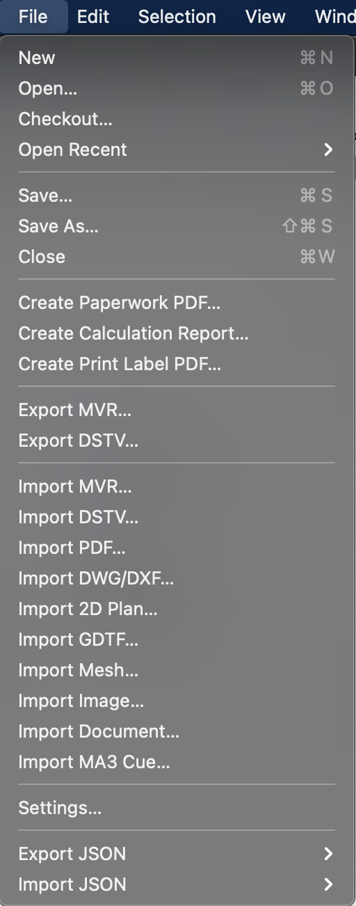
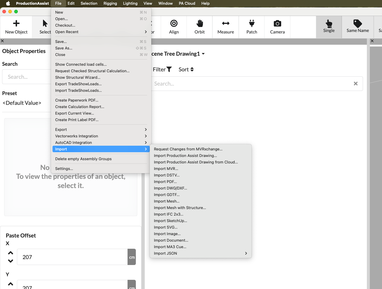
In the File menu you manage drawings, import and export data and access central output functions.
| Menu command | What happens | Requirement |
|---|---|---|
| New | Creates a new, empty drawing. | Desktop app or host integration, not just a browser view. |
| Open... | Opens an existing Production Assist drawing from your computer. | Access to a local file. |
| Open from PA Cloud... | Loads a drawing from an online project into your workstation. | Logged in account and access to a PA Cloud project. |
| Last opened | Opens an already used file directly from the recent files list. | At least one previously opened file. |
| Save... | Saves the current drawing to the existing file path. | Open drawing with write access. |
| Save as... | Saves the current drawing as a new file or with a new name. | Opened drawing. |
| Close | Closes the current drawing. | Opened drawing in the desktop app or host integration. |
| Menu command | What happens | Requirement |
|---|---|---|
| Show connected load measuring cells... | Opens the load cell dialog. There you can set up new load measuring cells and, for example, set the load measurement intervals. | The dialogue is visible to everyone. The actual use of the load cell functions is intended for Arena customers. |
| Request a verified statics calculation... | Opens the dialog to request an offer for an externally verified static calculation from our internal statics office. You can hand over a prepared drawing and the relevant calculation bases; our engineering office then takes over the testing and approval processes. When you request, you will receive an initial offer pricing based on your drawing, which you can include in the project budget in the preliminary planning. The statics office can then request further documents or clarifications if necessary. | Drawing with statically relevant data and usually internet access. |
| Show structure wizard... | Opens the structure wizard, which guides you step by step through the settings for line loads, wind loads and horizontal equivalent loads. The assistant explains which inputs are required, suggests sensible standard values and supports the preparation of the loads for the static calculation. | Opened drawing. |
| Export TradeShowLoads... | Exports load and measurement data in TradeShowLoads-JSON format for delivery to trade fair operators. The file contains all relevant loads and measured values so that the trade fair operator can import the data into their system to check hall supports and rigging. | Drawing contains load or measurement data; desired export parameters set. |
| Import TradeShowLoads... | Imports TradeShowLoads-JSON files from the trade fair operator and adopts the load values contained therein into the current drawing, e.g. B. for checking and validating hall supports. | Present TradeShowLoads-JSON file from the trade fair operator. |
| Export worksheets as PDF... | Creates a PDF from Worksheets and Assembly Sheets. Further details can be found in worksheets. | At least one Worksheet or Assembly Sheet in the drawing. |
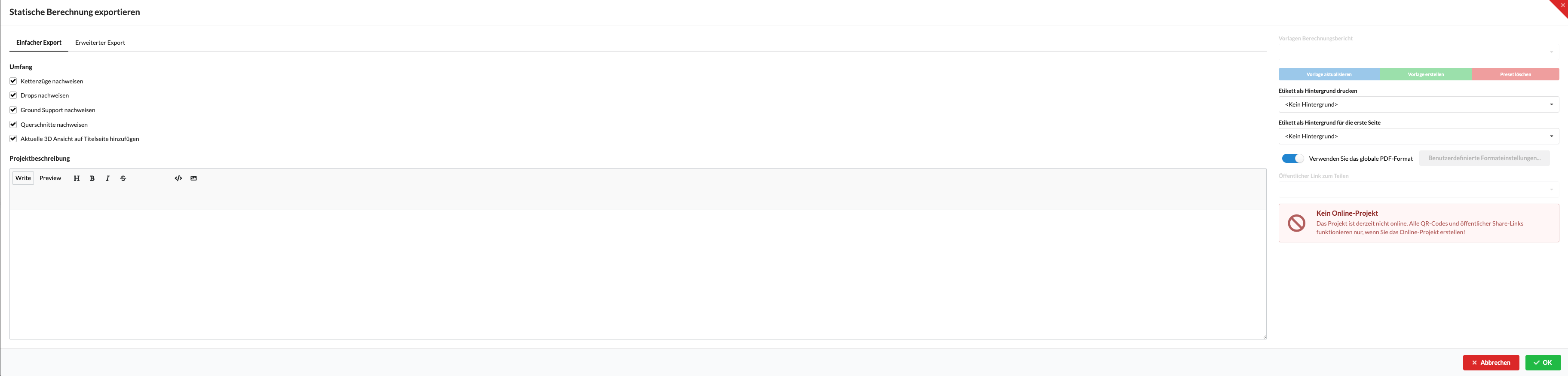
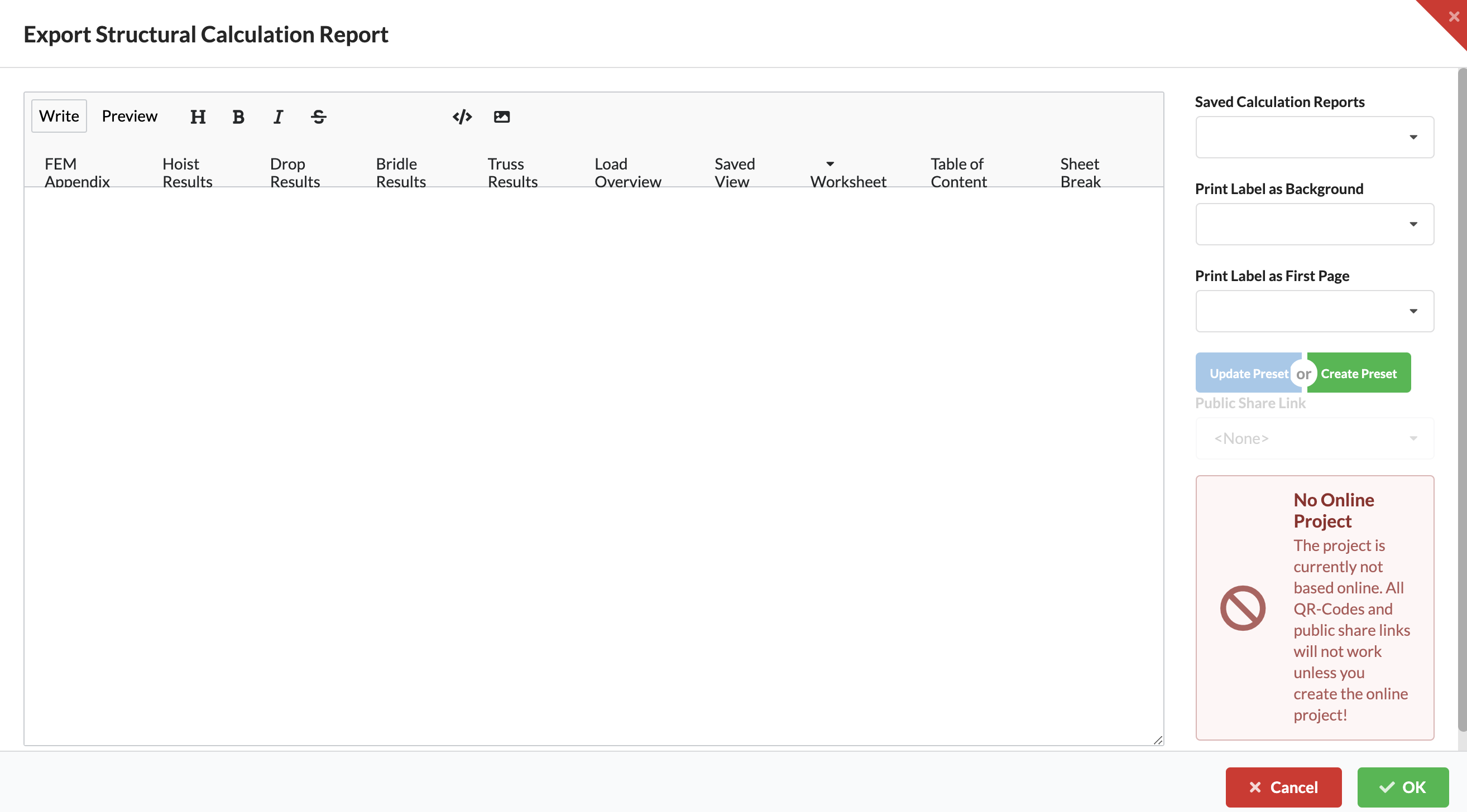
| Export calculation report as PDF... | Exports the static report with results and evidence. Further details can be found in staticcalculation. | A static calculation has been carried out or there are calculable results. |
| Export current view... | Saves the current Renderer view as a file. | Opened drawing with desired screen view. |
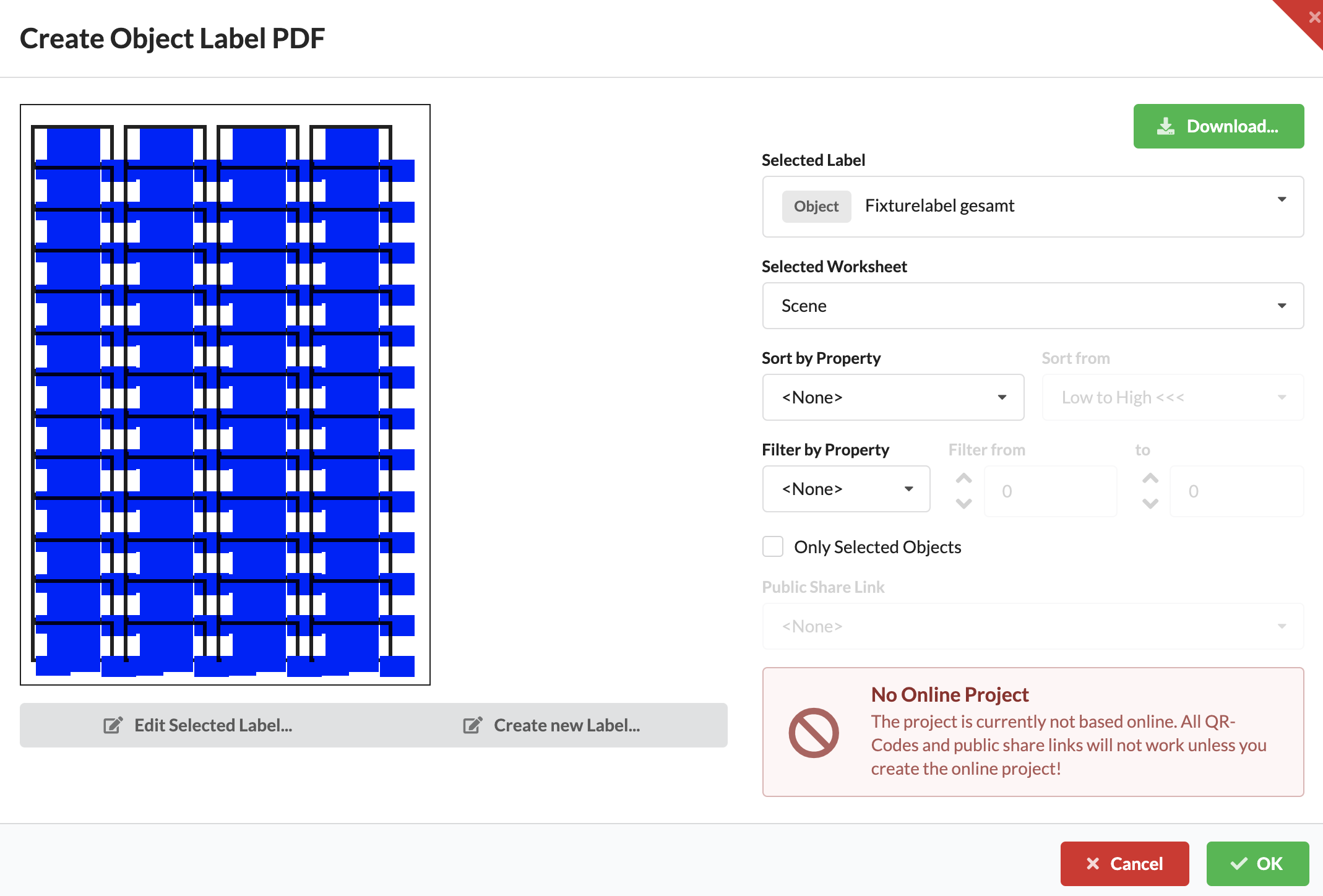
| Export labels as PDF... | Creates a printable PDF from existing label templates. Further details can be found in label creation. | Label templates or assigned label data exist. |
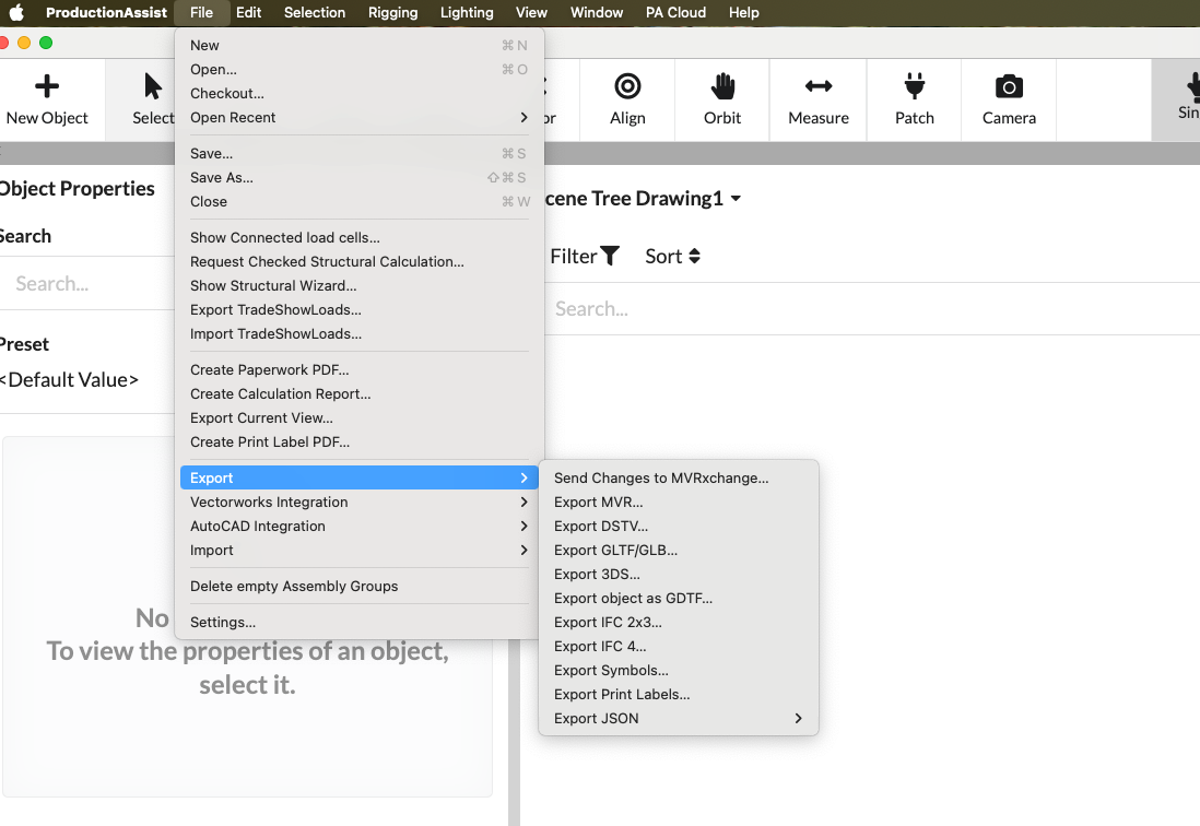
| Menu command | What happens | Requirement |
|---|---|---|
| Send changes to MVRxchange... | Commits your changes to MVRxchange as a new revision. | Linking to a MVRxchange project and internet access. |
| MVR export... | Exports the drawing as a MVR file for sharing with other systems. | Drawing with exportable MVR data. |
| DSTV export... | Exports appropriate steel or structural information as a DSTV file. | Drawing contains DSTV-relevant components. |
| Export GLTF/GLB... | Exports the scene as a 3D file in GLTF or GLB format. | Opened drawing with 3D content. |
| 3DS export... | Exports the scene as a 3DS file. | Opened drawing with 3D content. |
| Export object as GDTF... | Exports a suitable object or fixture as a GDTF file. | Matching fixture or symbol with sufficient device data. |
| IFC 2x3 export... | Exports the drawing in IFC 2x3 format. | IFC-capable geometry and desired exchange in the BIM context. |
| IFC 4 export... | Exports the drawing in IFC-4 format. | IFC-capable geometry and desired exchange in the BIM context. |
| Export symbols... | Exports symbol resources from the current drawing. | Existing symbol definitions. |
| Export Labels... | Exports print label resources for distribution or backup. | Existing label resources. |
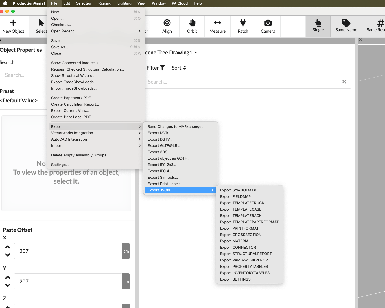
| Menu command | What happens | Requirement |
|---|---|---|
| Export SYMBOLMAP | Exports symbol mappings as a JSON file. | Existing symbol mappings in the drawing or library. |
| Export FIELDMAP | Exports field mappings as a JSON file. | Existing field definitions or mappings. |
| Export CONTAINER templates | Exports truck or container templates as JSON. | Existing container or truck templates. |
| Export CASE templates | Exports case templates as JSON. | Existing case templates. |
| Export RACK templates | Exports rack templates as JSON. | Existing rack templates. |
| Export PAPERFORMAT templates | Exports paper format templates as JSON. | Existing print or paper format templates. |
| Export PRINT FORMAT | Exports print formats as JSON. | Existing print formats. |
| Export CROSS SECTION | Exports cross-section definitions as JSON. | Existing cross-sectional data. |
| Export MATERIAL | Exports material definitions as JSON. | Existing material data. |
| Export CONNECTOR | Exports connector definitions as JSON. | Existing connector definitions. |
| Export STRUCTURAL REPORT | Exports structure report templates or data as JSON. | Existing report templates or exportable report data. |
| Export PAPERWORK REPORT | Exports Paperwork report templates or data as JSON. | Existing paperwork templates or report data. |
| Export PROPERTY TABLES | Exports property table templates as JSON. | Existing table templates. |
| Export INVENTORY TABLES | Exports inventory table templates as JSON. | Existing inventory tables or templates. |
| Export SETTINGS | Exports settings as a JSON file. | Exportable app, project or print settings. |
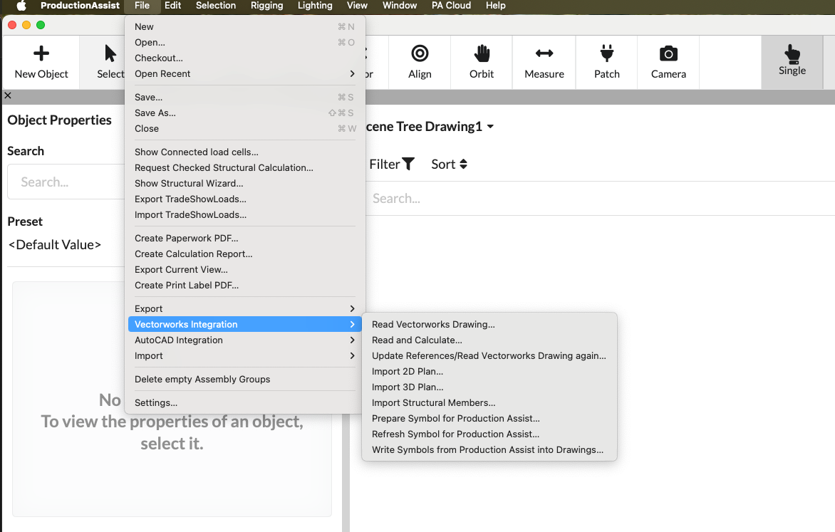
| Menu command | What happens | Requirement |
|---|---|---|
| Vectorworks read drawing... | Reads the current or linked Vectorworks drawing into Production Assist. | Active Vectorworks integration and accessible drawing data. |
| Read and Calculate... | Rereads the Vectorworks drawing and starts a static calculation directly. | Vectorworks integration and computable structural data. |
| Update references/reread plan... | Updates references or rereads host drawing. | Already linked Vectorworks data. |
| Import 2D plan... | Imports a 2D plan from the host application. | Active Vectorworks integration with appropriate plan content. |
| Import 3D plan... | Imports 3D geometry from the host application. | Active Vectorworks integration with 3D data. |
| Import beam structure... | Imports structural components from the host application. | Active integration and existing structure objects. |
| Prepare symbols for Production Assist... | Prepares host symbols for use in Production Assist. | Appropriate icons in the host application. |
| Update symbol for Production Assist... | Updates already prepared symbol definitions from the host application. | Existing, linked symbols. |
| Write symbols from Production Assist into drawing... | Writes symbol information from Production Assist back to the host drawing. | Active integration and target drawing with write access. |
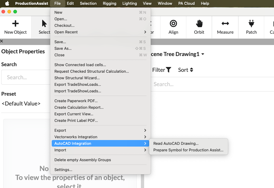
| Menu command | What happens | Requirement |
|---|---|---|
| Read AutoCAD Drawing... | Reads a AutoCAD drawing into Production Assist. | Active AutoCAD integration. |
| Prepare symbols for Production Assist... | Prepares AutoCAD symbols for use in Production Assist. | Appropriate blocks or symbols in AutoCAD. |
| Menu command | What happens | Requirement |
|---|---|---|
| Import changes from MVRxchange... | Brings new revisions or changes from MVRxchange into the current drawing. | Link to MVRxchange and internet access. |
| Production Assist Import drawing… | Imports content from another Production Assist drawing. | Present import file. |
| Production Assist Import drawing from the cloud... | Imports content directly from a cloud drawing. | Online project with corresponding source file. |
| MVR import... | Imports a MVR file into the current drawing. | Existing MVR file. |
| DSTV import... | Imports DSTV data into the current drawing. | Existing DSTV file. |
| PDF import... | Imports a PDF, for example as a plan background. | Existing PDF file. |
| Import DWG/DXF... | Imports a DWG or DXF file. | Desktop app with DWG or DXF file available. |
| GDTF import... | Imports a fixture profile in GDTF format. | Existing GDTF file. |
| Import Mesh... | Imports a single mesh file. | Present 3D file in a supported format. |
| Import mesh with structure... | Imports a complete mesh scene with hierarchy or structure reference. | Present scene file with structure information. |
| Import IFC 2x3... | Imports IFC data in 2x3 format. | Present IFC file. |
| Import SketchUp... | Imports a SketchUp model. | Existing SketchUp file. |
| Import SVG... | Imports vector graphics in SVG format. | Present SVG file. |
| Import image... | Imports an image as a resource or plan content. | Present image file. |
| Import document... | Imports an external document into the project. | Present file and desired project reference point. |
| Import MA3 cue... | Imports cue data from grandMA3. | Existing MA3 data or export file. |
| Menu command | What happens | Requirement |
|---|---|---|
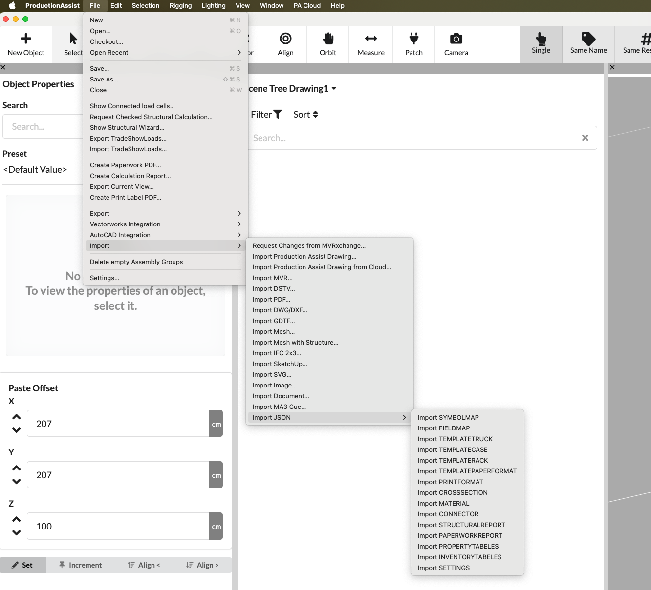
| Import JSON | Opens the general JSON import for supported data types. | Existing JSON file. |
| Import SYMBOLMAP | Imports symbol mappings from JSON. | Matching JSON file with symbol mappings. |
| Import FIELDMAP | Imports field mappings from JSON. | Matching JSON file with field definitions. |
| Import PRINT FORMAT | Imports print formats from JSON. | Matching JSON file with print formats. |
| Import CONTAINER templates | Imports truck or container templates from JSON. | Matching JSON file with templates. |
| Import CASE templates | Imports case templates from JSON. | Matching JSON file with templates. |
| Import RACK templates | Imports rack templates from JSON. | Matching JSON file with templates. |
| PAPER SIZE Import template | Imports paper format templates from JSON. | Matching JSON file with paper sizes. |
| Import CROSS SECTION | Imports cross-section definitions from JSON. | Matching JSON file with cross-sectional data. |
| Import MATERIAL | Imports material definitions from JSON. | Matching JSON file with material data. |
| Import CONNECTOR | Imports connector definitions from JSON. | Matching JSON file with connector data. |
| Import STRUCTURAL REPORT | Imports structural report templates or report data from JSON. | Matching JSON file with report data. |
| Import PAPERWORK REPORT | Imports paperwork templates or report data from JSON. | Matching JSON file with report data. |
| Import PROPERTY TABLES | Imports property table templates from JSON. | Matching JSON file with table templates. |
| Import INVENTORY TABLES | Imports inventory table templates from JSON. | Matching JSON file with inventory data or templates. |
| Import SETTINGS | Imports saved settings from JSON. | Matching JSON file with compatible settings. |
| Menu command | What happens | Requirement |
|---|---|---|
| Delete empty assemblies | Removes Assembly Groups without content from the Scene Tree. | Drawing with empty assemblies. |
| Settings... | Opens the general app, project and print settings. | Open drawing or accessible application settings. |
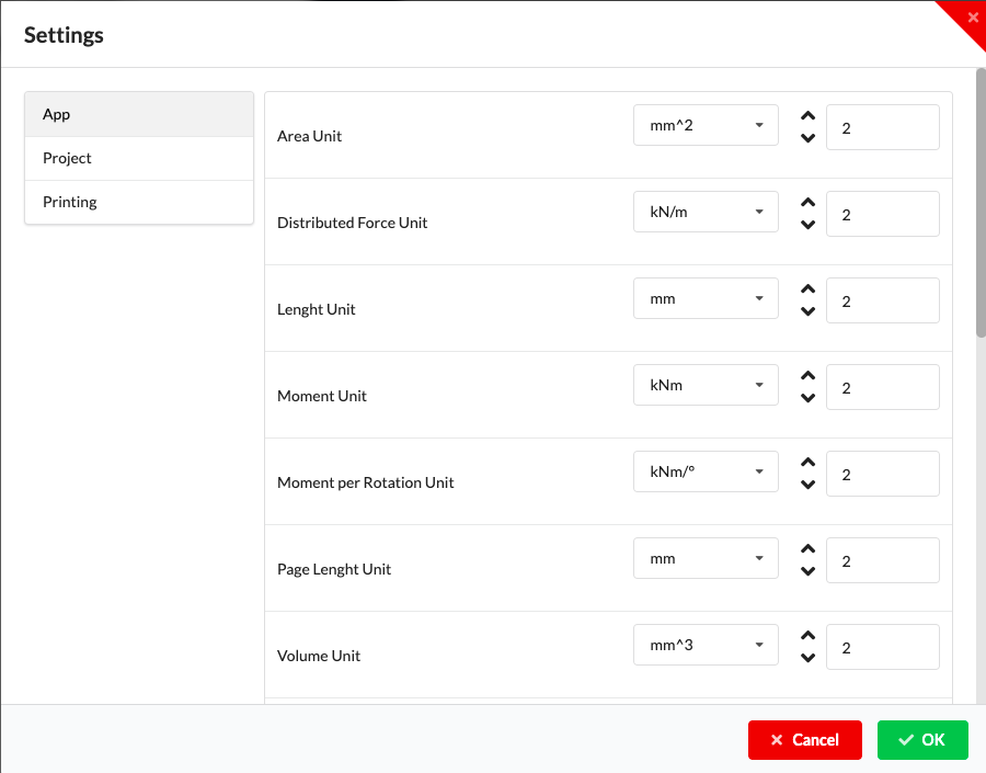
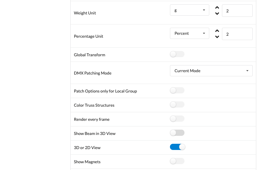

Important settings in this dialog include units, display options, rendering behavior, visibility of magnets, display of static hints, and patching behavior.
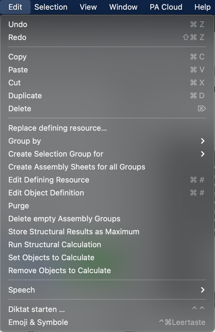
The Edit menu contains commands for modifying, renaming, and structuring your drawing.
| Menu command | What happens | Requirement |
|---|---|---|
| Undo | Undoes the last change step. | There is a reversible change. |
| Repeat | Redoes a previously undone step. | There is a redo-enabled step. |
| Copy | Copies the current selection to the clipboard. | At least one selected object. |
| Insert | Pastes the contents of the clipboard. | Appropriate clipboard content. |
| Cut out | Removes the selection and places it on the clipboard. | At least one selected object. |
| Duplicate | Creates a copy of the selected objects. | At least one selected object. |
| Delete | Deletes the selected objects. | At least one selected object. |
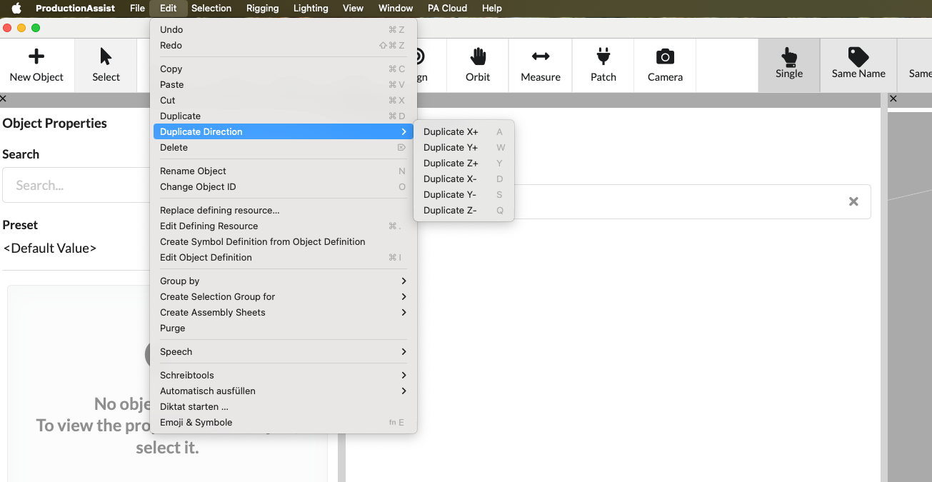
These commands make it easy to automatically move predefined sets of objects along an existing structure. For example, if a truss with a length of 5 m is selected as the target structure, the respective duplicate/move action automatically moves the selected objects by this length. This means that complex drawings - especially with layers or recurring constructions - can be created very quickly. The actual displacement length used is displayed in the Object Info Palette (bottom left).
| Menu command | What happens | Requirement |
|---|---|---|
| Duplicate X+ | Duplicates the selection in the positive X direction. | At least one selected object. |
| Duplicate Y+ | Duplicates the selection in the positive Y direction. | At least one selected object. |
| Duplicate Z+ | Duplicates the selection in the positive Z direction. | At least one selected object. |
| Duplicate X | Duplicates the selection in the negative X direction. | At least one selected object. |
| Duplicate Y | Duplicates the selection in the negative Y direction. | At least one selected object. |
| Duplicate Z | Duplicates the selection in the negative Z direction. | At least one selected object. |
| Menu command | What happens | Requirement |
|---|---|---|
| Change object name | Activates the name field of the selected object for direct editing. | Exactly one object or a unique selection. |
| Change object ID | Enables the ID field of the selected object for direct editing. | Exactly one object or a unique selection. |
| Replace defining resource... | Replaces the underlying resource of a selected object. | Selection with replaceable resource. |
| Edit defining resource | Opens the resource of a selected object in edit mode. | Object with editable resource. |
| Create symbol definition from object | Creates a new symbol definition from the selected object. | Selection with appropriate object or geometry. |
| Edit object definition | Opens the object definition of the selected element for editing. | Object with editable definition. |
| Menu command | What happens | Requirement |
|---|---|---|
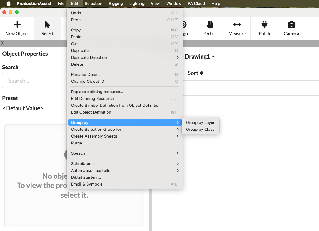
| Group by | Opens commands for structured grouping in Scene Tree. | Opened drawing. |
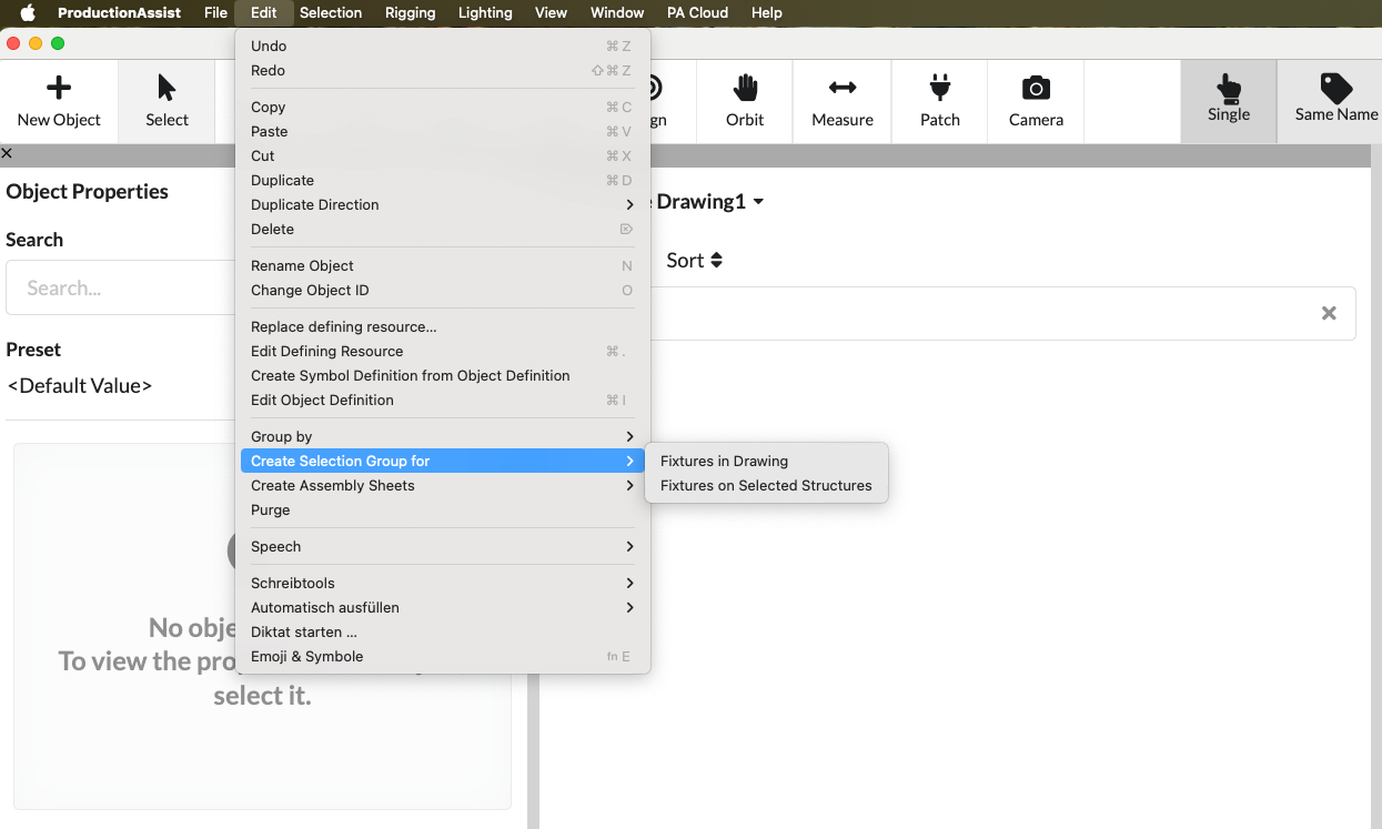
| Create selection group for | Automatically creates selection groups for related fixtures. | Matching fixtures in the drawing. |
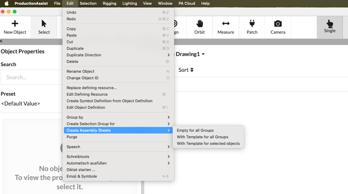
| Create assembly sheets | Creates Assembly Sheets for groups or selected objects. | Existing assemblies or suitable selection. |
| Clean up | Removes objects, classes, or resources that are no longer used. | Drawing with unused entries. |
| Menu command | What happens | Requirement |
|---|---|---|
| Group by level | Creates groups in Scene Tree based on layers. | Existing objects with layer mapping. |
| Group by class | Creates groups in Scene Tree based on classes. | Existing objects with class assignment. |
| Menu command | What happens | Requirement |
|---|---|---|
| Fixtures in the drawing | Creates a selection group for all fixtures of the same type throughout the drawing. | At least one fixture as initial selection. |
| Fixtures on the selected structures | Creates a selection group for fixtures on the selected structures. | Selected structure and associated fixtures. |
| Menu command | What happens | Requirement |
|---|---|---|
| without template for all assemblies | Creates empty Assembly Sheets for all groups. | Existing assemblies. |
| with template for all assemblies | Creates Assembly Sheets for all groups based on a template. | Existing assemblies and at least one suitable template. |
| with template for selected objects | Creates Assembly Sheets from the current selection using template. | Appropriate selection and at least one suitable template. |
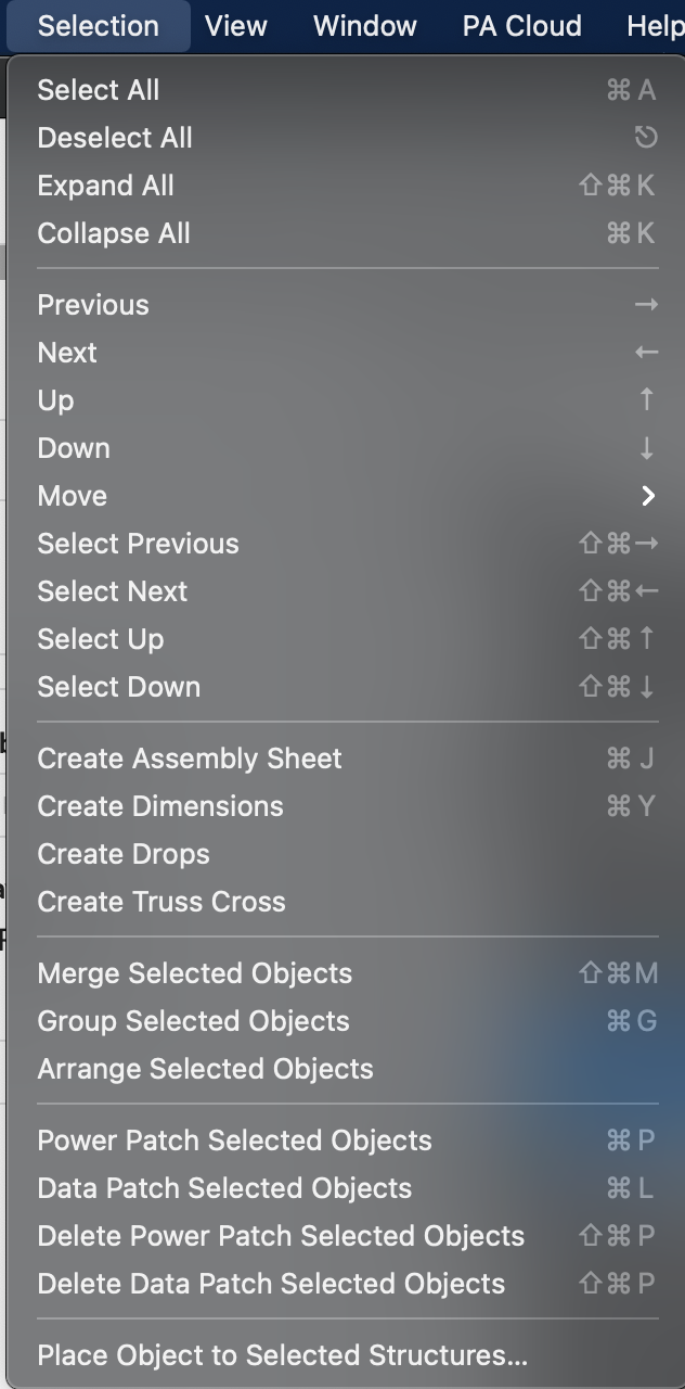
In the Selection menu you control the object selection, create subsequent objects and execute commands directly on selected elements.
| Menu command | What happens | Requirement |
|---|---|---|
| Select all | Selects all objects in the drawing. | Opened drawing. |
| Deselect everyone | Clears the current selection completely. | At least one selected object. |
| Expand all | Expands all groups in Scene Tree. | Groups or tree structure available. |
| Collapse all | Collapses all groups in Scene Tree. | Groups or tree structure available. |
| Select previous object | Jumps to the previous selection position. | Navigable object structure available. |
| Select next object | Jumps to the next selection position. | Navigable object structure available. |
| Select parent object | Goes to the higher level in the object tree. | Currently selected object with parent structure. |
| Select child object | Goes to a child object. | Currently selected object with child objects. |
| Add previous object to selection | Adds the previous object in addition to the selection. | Navigable object structure available. |
| Add next object to selection | Adds the next object in addition to the selection. | Navigable object structure available. |
| Add top object to selection | Adds the parent object in addition to the selection. | Selected object with parent structure. |
| Add lower object to selection | Adds a child object in addition to the selection. | Selected object with child objects. |
| Menu command | What happens | Requirement |
|---|---|---|
| Create assembly sheet | Creates a Assembly Sheet from the current selection. Further details can be found in tutorial_create_patch_table. | Sensible selection of objects or groups. |
| Create dimension | Creates an automatic dimension for the selection. | Appropriate geometric selection, for example a structure. |
| Merge selected objects | Combines several selected objects into one object. | Multiple compatible objects selected. |
| Group selected objects into assembly | Creates a new Assembly Group from the selection. | Multiple or single groupable objects selected. |
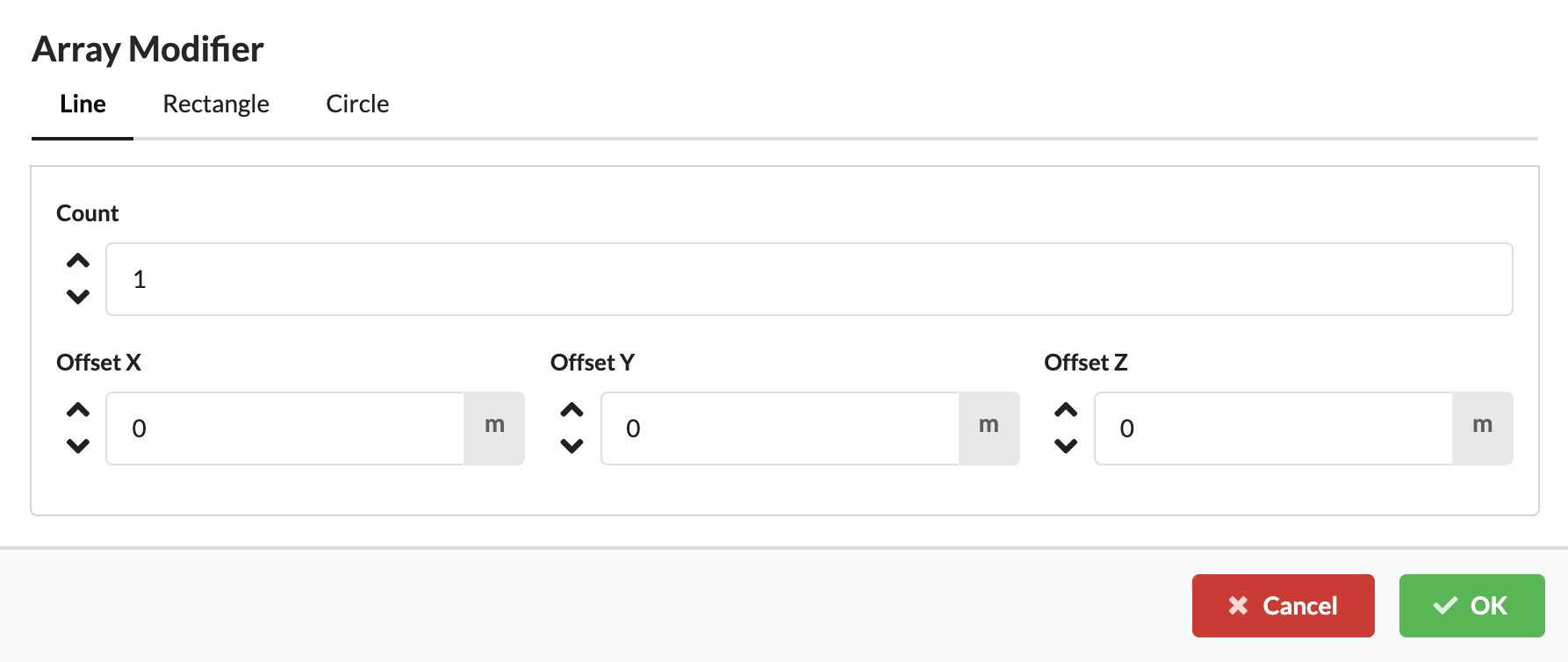
| Arrange selected objects | Duplicates and distributes the selection according to a defined pattern. | Appropriate output selection. |
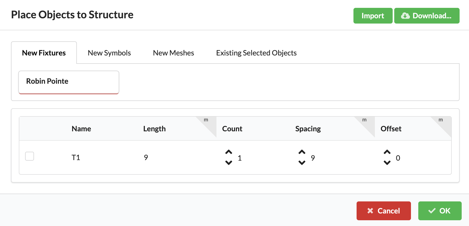
| Place objects on selected structures... | Places objects evenly along a selected structure. | At least one target structure and placeable objects. |
| Menu command | What happens | Requirement |
|---|---|---|
| Move selected objects to the right | Moves the selection by a fixed amount in the positive X direction. | At least one selected object. |
| Move selected objects to the left | Moves the selection by a fixed amount in the negative X direction. | At least one selected object. |
| Move selected objects forward | Moves the selection by a fixed amount in the positive Y direction. | At least one selected object. |
| Move selected objects back | Moves the selection by a fixed amount in the negative Y direction. | At least one selected object. |
| Move selected objects up | Moves the selection by a fixed amount in the positive Z direction. | At least one selected object. |
| Move selected objects down | Moves the selection by a fixed amount in the negative Z direction. | At least one selected object. |
In the Rigging menu you will find static calculations, structural tools and commands for slings, loads and tests.
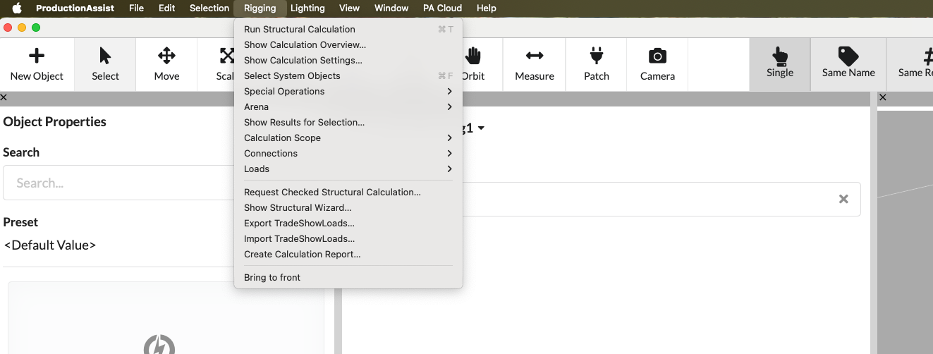
| Menu command | What happens | Requirement |
|---|---|---|
| Read and Calculate... | Rereads the host drawing and immediately starts the static calculation. | Only in the Vectorworks integration with an existing drawing. |
| Calculate statics | Starts a new static calculation for the current drawing or the selected calculation scope. Can be started manually even if real-time calculation is disabled — useful for specifically triggering a recalculation. | Opened drawing with statically relevant objects. |
| Show calculation overview... | Shows all relevant parameters that are included in the static calculation (e.g. loads, wind loads) as well as the individual verifications for Drops and cross sections. This makes it easy to check results and evidence. | Existing calculation results or computable scene. |
| Show calculation settings... | Opens the dialog with settings for the static calculation. Here you can fine-tune parameters such as wind loads, safety factors, load case combinations and other calculation parameters. The same dialog can also be accessed via the calculation navigation (e.g. load case combinations); this menu command opens it directly. | Opened drawing. |
| Select system objects | Marks a selected truss element and automatically selects all trusses connected to it. Very practical if related trusses need to be moved or edited together. Requirement: The starting object must actually be a traverse. | Drawing with structures or system objects. |
| Show results for selection... | Opens a dialog with a results view for the selected structural element. Shows detailed curves of cutting reactions (e.g. moments, shear forces, normal forces) as graphics and numerical values for individual points so that each verification value can be checked precisely. | Selected, already calculated objects. |
| Request a verified statics calculation... | The request for externally tested statics starts with our internal engineering office. The office takes over the audit service and the technical audit responsibility according to the offer; After placing the order, you will immediately receive a test order code/reference for tracking. | Computable drawing and usually internet access. |
| Request a verified statics calculation... | The request for externally tested statics starts with our internal engineering office. After the request you will receive a reference for follow-up; Further documents can be requested if necessary. | Computable drawing and usually internet access. |
| Show structure wizard... | Opens the wizard for rigging-specific workflows. | Opened drawing. |
| Export TradeShowLoads... | Exports load and measurement data in TradeShowLoads-JSON format. The file contains the necessary measured values and metadata for exchange with trade fair or testing services. | Load data present in the drawing. |
| Import TradeShowLoads... | Imports TradeShowLoads-JSON files and transfers the included load and measurement values into the drawing. Existing loads are supplemented or optionally overwritten; Incompatible or missing entries are logged and displayed during import. | Existing, compatible TradeShowLoads-JSON file. |
| Export calculation report as PDF... | Exports the statics results as a report. | Existing calculation results. |
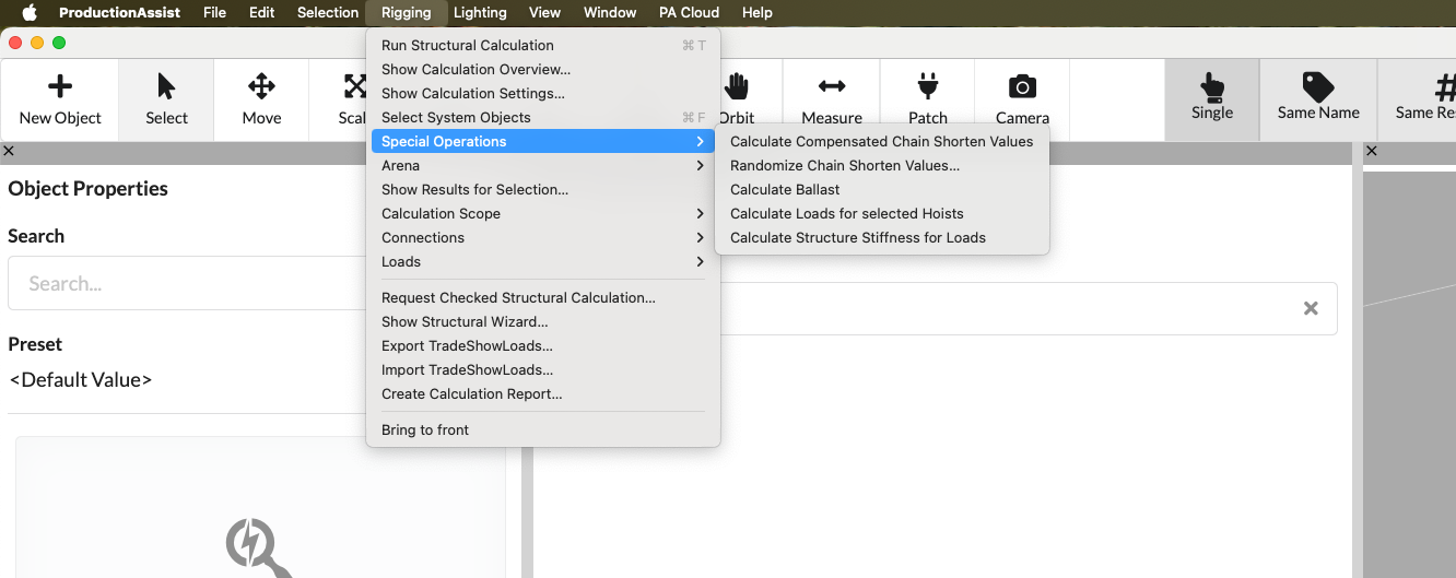
| Menu command | What happens | Requirement |
|---|---|---|
| Calculate compensated chain shortening | Takes chain shortening into account to compensate for the deflection of the Drops. The compensation can be started manually via this menu or activated in the settings so that it is applied automatically after each static calculation run. | Suitable rigging objects, for example Hoists or anchor points. |
| Generate chain shortening values randomly... | Assigns random chain truncation values within defined upper and lower limits. The values are not compensated for, but are used to simulate unleveled or incorrect settings - very practical for observing the behavior of the system under incorrect conditions or during stress tests. | Existing chain shortenings or compatible rigging objects. |
| Calculate ballast | Calculates the required ballast for ground support systems. The calculation uses the ballast program / support attachment and takes loads from all directions into account, so that the maximum required ballast for the entire system is determined. | Ground support structure with loads. |
| Calculate loads for selected bearing | Calculates for the selected chain hoist/Hoist what proportion (in percent) of each load goes into this chain hoist and uses this to determine the resulting weight per chain hoist. Requirement: A single chain hoist/Hoist must be selected. The results are displayed in the Worksheets and provide the per chain hoist weight for analysis. | Selection of suitable Hoists or bearings. |
| Determine structural stiffness of loads | Determines the effective stiffness of the structure for individual loads and shows how the structure would behave (e.g. lowering) if the respective load was doubled. This makes it possible to assess whether moving fixtures (e.g. lamps) could cause major vibrations or unwanted movements at this point. The results are output per load in Worksheets and provide the values necessary for the analysis. | Suitable load objects with static reference. |
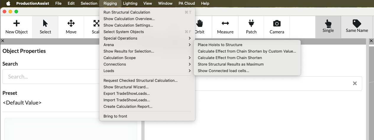
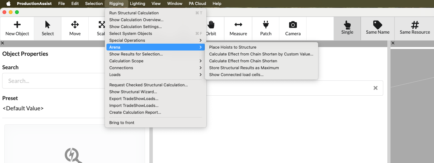
| Menu command | What happens | Requirement |
|---|---|---|
| Place Hoists to Structure | Starts the AI-powered placement algorithm for chain hoists: select elements (or nothing, then the entire drawing is taken into account), optionally enter ceiling loads/load specifications and the AI determines optimal hanging point positions taking the ceiling loads into account. In the object properties you can also restrict which elements are included in the placement. | Suitable structure and Hoist data (if selected: marked elements). |
| Calculate chain shortening effect with value... | Evaluates how the utilization and stress of a chain hoist or structural element increases when the leveling position (chain length) is changed. Opens a dialog where you enter a delta in millimeters; the system moves the elements accordingly and calculates the resulting load and utilization changes. Imagine it like a mobile: you pull at one point and check how strongly the entire system reacts. Note: Feature only in the Arena version; You can find settings and results in the calculation overview. | Suitable rigging situation with chain shortening. |
| Calculate chain shortening effect | Evaluates the impact of current chain cuts using a fixed standard delta of 30 mm (3 cm). Doesn't open a settings dialog - the shift delta is fixed; the calculation shows the resulting changes in loads and utilization. Imagine it like a mobile: you pull at one point and check how strongly the system reacts. Note: Only in the Arena version; Results appear in the load case “UL” in the calculation overview. | Existing Chain-Shorten values. |
| Save statics results as maximum | (Arena) Executes a current static calculation and saves the maximum cutting reactions of the affected structural elements directly in their geometry. For example, the maximum load situation of a structural hall can be saved and later reused for verification or comparisons. | Existing calculation results, Arena license. |
| Show connected load measuring cells... | Opens the load cell dialog. There you can set up new load measuring cells and, for example, set the load measurement intervals. | The dialogue is visible to everyone. The actual use of the load cell functions is intended for Arena customers. |
The following commands control which objects are included in the static calculation. With "Select objects for calculation" the currently marked objects are included in the calculation scope and visible as entries marked red in Scene Tree. All child objects are automatically included. This is useful if you only want to specifically calculate a part of the system or create an overview for a section of the system. With "Reset objects for calculation" you remove the marking again and remove the objects from the scope of the calculation.
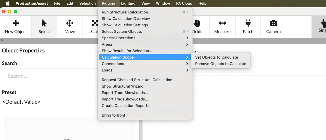
| Menu command | What happens | Requirement |
|---|---|---|
| Select objects for calculation | Includes the current selection in the calculation scope. | Selected objects or groups. |
| Reset objects for calculation | Removes the selection from the calculation scope. | Already defined calculation scope or selected calculation objects. |
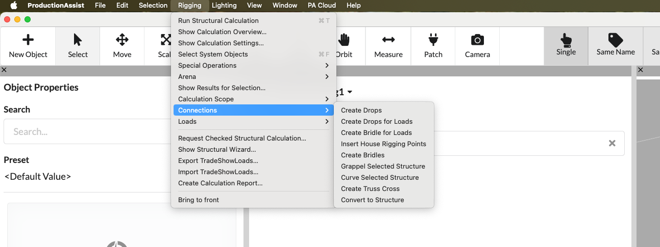
| Menu command | What happens | Requirement |
|---|---|---|
| Create Drops | Inserts Drops between the selected structural elements: Select the structural elements that should be connected, then a dialog opens for selecting the chain hoist/Hoist symbol to be used and associated parameters. After selection, a drop with the appropriate chain length and the correct properties is inserted in all relevant places. Important: At least one suitable chain hoist/Hoist must already be present in the drawing. | Appropriate structure selection; existing chain hoist/Hoist in the drawing. |
| Create Drops for Loads | Select load objects; the tool finds the nearest structural element above (e.g. truss) and inserts a drop between the load and the structure. A dialog shows the chain hoist/Hoist used and associated parameters for control. Particularly practical for existing loads under existing structures. | Selected load objects; suitable structural elements nearby. |
| Create Bridle for Loads | Uses both the selected load object and the structural element above it: The tool connects start and end nodes of the structural element above with a Bridle between load and structure. After selection, a dialog opens in which the used lifting points/chain hoists and parameters can be checked and adjusted. Particularly practical when existing loads need to be suspended directly under structures. | Selected load objects; suitable overlying structural element and anchor points. |
| Insert house anchor points | Automatically inserts house rigging points at the chain/structure points above them. The tool creates anchor points, accepts or allows the entry of load capacities and orientations and, if necessary, combines several points (e.g. in a roof area) so that combined load capacities are displayed. Practical for quickly defining insertion locations for slings and making their load assumptions visible. | Existing top chains/structural elements or suitable insertion areas in the drawing. |
| Bridle generate | When a chain hoist/Hoist is selected, the tool automatically creates two Bridle legs that connect the chain hoist to the structural elements above it. A dialog allows the selection/checking of the attachment points, adjustment of parameters and control of the load assumptions. Practical if chain hoists already exist in the drawing and stop connections need to be created quickly. | Existing chain hoist/Hoist and suitable attachment points/structural elements. |
| Grappel Selected structure | Creates bolted connections (Grapples) between trusses and other structural elements. Opens a dialog for entering or selecting the desired resilience; Production Assist then uses the structure extensions to automatically calculate and apply required reinforcements, fastening parameters and load capacities. Practical for quickly connecting several trusses with standardized screw connections and suitable load assumptions. | Selected structure. |
| Curve selected structure | Automatically creates a curved structure between two selected truss elements: Select the two truss nodes (start and end), then the tool creates the curved connection and adjusts segment lengths and transition points. A short dialog allows you to set the radii of curvature, number of segments and alignment options. Works analogously to the Drop/Bridle tools and is practical for quickly connecting existing trusses to curved segments. | Two truss nodes or suitable structural segments selected. |
| Create Traskos automatically | Automatically inserts a connection (Traskos) between two selected structural elements. The connection can be designed to be either flexible or rigid; Before creation, a short dialog opens in which you specify the connection type, radius of curvature, number of segments and stiffness parameters. Practical for quickly creating connecting elements with the desired rigidity. | Two truss nodes or suitable structural segments selected. |
| Convert to structure | Converts selected objects to structural objects. Lines that belong to an object are automatically converted into structural elements. This is practical if structural elements already exist (e.g. after an import) and you want to quickly convert lines into load-bearing structural parts. | Appropriate objects or line selection. |
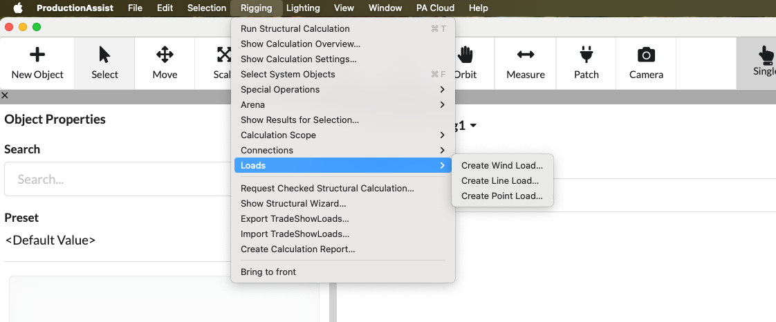
| Menu command | What happens | Requirement |
|---|---|---|
| Create wind load... | Creates a wind load for the structure. Note: This menu item is deprecated and should normally no longer be used - use wind load management via the Berechnungseinstellungen or the wind load workflow in the calculation overview instead. The entry is retained for compatibility reasons for legacy scenarios. | Opened drawing with suitable location. |
| Create line load... | Opens a dialog for creating a distributed load on selected structural elements. In the dialog you can choose between the global coordinate system and the local element coordinate system; You then enter the load components in X/Y/Z (as distributed force per unit length) and see a preview of the resulting distribution. | Appropriate structure or load situation. |
| Create point load... | Opens a dialog for creating point loads on the selected structural elements. Here you can enter the load type and the components in After confirmation, a point load is applied to each selected structural element; The preview in the dialog shows the positioning before inserting. | Appropriate structure or load situation; marked target objects. |
In the Lighting menu you manage power and data connections for fixtures and other consumers.
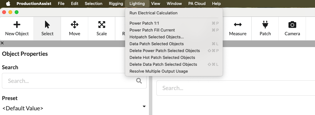
| Menu command | What happens | Requirement |
|---|---|---|
| Electrical calculation | Starts the electrical calculation and updates the network planning. By default, the electrical calculation runs continuously in the background; With this menu item you can start the calculation manually if necessary (e.g. after major changes) to receive updated results immediately. | Drawing with electrical consumers or distributors. |
| Power patch 1:1 | Pairs the selected power distributors and consumers and assigns each consumer a dedicated output point, creating a 1:1 assignment of the outputs. The assignment is made in selection order; unassigned overhangs are displayed in the log. | Selection of compatible distributors and consumers. |
| Power patch refill | Assigns selected loads to available outputs of the selected distributors one after the other until the electrical capacity of the distributors is reached. The tool fills outputs until configured protection thresholds/load limits (in the electrical settings) are reached; remaining consumers remain unassigned and are logged. | Selection of compatible distributors and consumers with free outputs. |
| Hotpatch Selected objects... | Starts Hotpatching for selected electrical systems: select a distributor that is Hotpatch‑capable and the command opens an internal patch dialog window. In the dialog you can assign outputs and loads interactively, check automatic suggestions, take into account load/protection thresholds from the electrical settings and see a preview of the assignments; After confirmation, the connections are applied immediately. | Suitable selection with patchable devices and at least one Hotpatch‑capable distributor. |
| Data Patch | Connects selected devices to data or DMX outputs. | Selection of compatible devices and data distributors. |
| Delete power patch | Removes all power patch connections from the current selection. Use this command to delete existing power assignments (patch connections) for the selected consumers or distributors; Affected consumers are removed from their assigned outputs and listed in the log. | Selection with existing power connections. |
| Hotpatch delete selected objects | Undoes Hotpatch connections of the current selection and restores the original 1:1 patching (each load is assigned its default output again). Handy for resetting temporary Hotpatches. | Selection with existing Hotpatch connections. |
| Delete data patch | Removes data/DMX connections (e.g. XLR/DMX, Ethernet, HDMI) of the current selection. Use this command to delete all data cable associations of the selected devices; remote connections are displayed in the log. | Selection with existing data connections. |
| Resolve duplicate connections | Opens a dialog for recognizing and resolving multiple occupied outputs. The dialog lists all conflicts (e.g. several consumers on the same output) and offers options: remove individual connections, automatically redistribute consumers to free outputs, or distribute them specifically to several physical sockets / Y splitters. Once confirmed, the changes are applied and a log shows the adjustments made. | Drawing with colliding or double connections. |
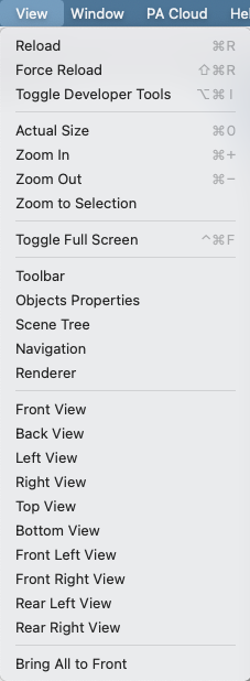
In the View menu you control the display in Renderer and show or hide work areas.
| Menu command | What happens | Requirement |
|---|---|---|
| Reset zoom | Resets the UI window zoom level to the default value. This resets the scaling of the user interface (font sizes, symbols and layout); Impact is complete in the desktop/Electron app, in embedded browsers or plugins depending on the host. | Supported desktop or Electron view; in plugins depending on the browser host. |
| Enlarge | Increases the UI zoom level (font sizes, symbols and UI elements are displayed larger), useful for better readability. Works in the desktop/Electron app; in embedded browsers/plugins, support depends on the host. | Supported desktop or Electron view; in plugins depending on the browser host. |
| Zoom out | Reduces the UI zoom level (font sizes, symbols and UI elements are displayed smaller) to make more content visible. Works in the desktop/Electron app; in embedded browsers/plugins, support depends on the host. | Supported desktop or Electron view; in plugins depending on the browser host. |
| Toggle full screen | Switches the application to full-screen mode: the active window is brought to the foreground to fill the screen, ideal for focused work without distractions. Note: Full screen mode is per window — if you have multiple windows open, you'll need to switch between them. Works reliably in the desktop/Electron app; In embedded browsers or plugins, the behavior depends on the host. | Supported desktop or Electron view; in plugins depending on the browser host. |
| Zoom to selection | Centers the Renderer on the current selection (single object or multiple objects). Very practical for finding an object in 3D‑Renderer — e.g. B. after a search in Scene Tree, by clicking on the object or using the assigned shortcut. | At least one selected object. |
| Connect to VR headset... | Opens the connection settings for VR. Production Assist calculates the necessary 3D settings and streams the Renderer view to a compatible headset. The connection is typically made by scanning the QR code that the app displays; The current view is then displayed in the headset. | VR‑enabled environment and supported hardware. |
With these commands you control the visibility of the individual UI areas (tiles/panels) of Production Assist. For example, you can show and unhide the toolbar (the main tools for editing), the object properties panel (for viewing and editing object parameters) or the Renderer. Enabled areas are restored to the last used position - useful if you accidentally closed areas or want to temporarily adjust the layout.
| Menu command | What happens | Requirement |
|---|---|---|
| Toolbar | Shows or hides the toolbar. | Opened drawing. |
| Object properties | Shows or hides the object properties. | Opened drawing. |
| structure | Shows or hides the Scene Tree. | Opened drawing. |
| navigation | Shows or hides the navigation area. | Opened drawing. |
| Renderer | Shows or hides the Renderer area. | Opened drawing. |
The standard views quickly switch between predefined camera positions (front, back, side, top view, etc.). When switching, the current selection is automatically zoomed in; if there is no selection, the view is set so that the entire scene is visible. The views are also accessible via the number pad layout (NumPad 1–9) and enable quick switching between 2D and 3D perspectives. Use the number keys for direct shortcuts to the respective views.
| Menu command | What happens | Requirement |
|---|---|---|
| Front view | Changes the Renderer to the front view. | Opened drawing with visible scene. |
| Rear view | Switches the Renderer to the rear view. | Opened drawing with visible scene. |
| View from the left | Switches the Renderer to the left side view. | Opened drawing with visible scene. |
| View from the right | Changes the Renderer to the right side view. | Opened drawing with visible scene. |
| View from above | Changes the Renderer to the top view. | Opened drawing with visible scene. |
| View from below | Changes the Renderer to the bottom view. | Opened drawing with visible scene. |
| View from the front left | Switches to an isometric view from the front left. | Opened drawing with visible scene. |
| View from the front right | Switches to an isometric view from the front right. | Opened drawing with visible scene. |
| Rear left view | Switches to an isometric view from the back left. | Opened drawing with visible scene. |
| Rear right view | Switches to an isometric view from the back right. | Opened drawing with visible scene. |
| Isometric view | Switches between isometric and orthogonal display. | Opened drawing with visible scene. |
| Menu command | What happens | Requirement |
|---|---|---|
| Reload window | Reloads the current window view. | Desktop-App. |
| Open developer tools... | Opens the window's developer tools. | Desktop app, mostly for support or analysis. |
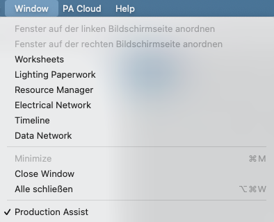
In the "Window" menu you control which additional work windows are opened parallel to the 3D‑Renderer. For example, in the desktop app, you can place Worksheets, Lighting Paperwork, or the Resource Manager as standalone windows next to Renderer — convenient for working on the drawing and related documents at the same time. Use the following commands to specifically show or open these windows.
| Menu command | What happens | Requirement |
|---|---|---|
| Worksheets | Opens the window with Worksheets and Assembly Sheets. | Opened drawing. |
| Illumination papers | Opens the Lighting-Paperwork window. | Opened drawing. |
| Resource Manager | Opens the Resource Manager. | Opened drawing. |
| cabling | Opens the electrical network window. | Drawing with electrical objects or opened drawing. |
| schedule | Opens the timeline window. | Opened drawing. |
| DMX Overview | Opens the data network or DMX window. | Drawing with DMX or data objects or open drawing. |
| Minimize | Minimizes the active window. | Desktop-App. |
| Bring everyone forward | Brings all program windows to the foreground. | macOS multi-window desktop app. |
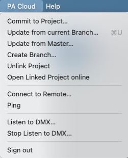
In the PA Cloud menu you will find commands for saving and collaborating in the cloud. With PA Cloud you can store drawings online, work on a project with others in real time, and track changes. Production Assist logs individual property changes and performs automatic merge/conflict assistance so that multiple people can work on different objects at the same time (e.g. one draws rigging, another creates the patch, a third performs structural calculations). Further background information and processes can be found in online workflow.
| Menu command | What happens | Requirement |
|---|---|---|
| Transfer changes... | Opens the dialog for transferring your local changes to the linked online project or for creating a new project. The changed properties are listed individually for each object in the dialog; you can choose which changes to transfer. If no online project is yet linked, the dialog offers to create a new project. Uploading is also a prerequisite for passing the drawing on to external services (e.g. our statics office) for review. | Linked online project or permission to create a new project; appropriate write permissions. |
| Synchronize workspace changes | Gets changes from the current branch and compares them with your status. | Linked branch or workspace. |
| Update current workspace from master... | Updates your current workspace with the status of the master branch. | Linked project with master branch. |
| Update from template... | Updates the project or workspace from a template. | Available template and corresponding access. |
| Create workspace | Creates a new workspace or branch. | Linked online project with branch rights. |
| Unlink project | Separates the local file from the currently linked online project. The local file remains intact; Changes will then no longer be automatically transferred to the online project and you will no longer receive remote updates. Before undoing, you should commit important changes or create a local backup. To reconnect, use the "Transmit changes..." command or relink the project in the PA Cloud dialog. | Local file is linked to a project. |
| Open linked project online | Opens the project page in the browser. | Linked online project. |
| View project calendar | Opens the project calendar of the linked project. | Online project with calendar access. |
| Commit changes for resource | Commits changes to a resource file to the project. | Edited resource with online link. |
| Download all online resources | Loads all available online resources into the local environment. | Internet access and project access. |
| Add user to project | Opens the dialog for inviting additional people to the project. | Project with administration or release rights. |
| Share project link… | Creates or shows a link to share the project. | Linked project and sharing permission. |
| Connect to PA-NET | Connects the app to other instances or devices via PA NET. Further details can be found in panet. | Network access and reachable remote station. |
| Log out | Signs out of your Production Assist account. | Logged in user account. |
The Help menu contains support, information, and installation commands.

| Menu command | What happens | Requirement |
|---|---|---|
| About Production Assist | Opens information about the installed version and application. | No special requirement. |
| Check for update | Checks whether a newer version is available. | Desktop app with internet access. |
| First steps... | Starts the First-Steps-Tour again. | No special requirement. |
| Open Discord community… | Opens the Discord server from Production Assist. | Internetzugang. |
| Open online help... | Opens the online manual. | Internetzugang. |
| Open online glossary... | Opens the online documentation glossary. | Internetzugang. |
| Edit keyboard shortcut... | Opens the dialog for viewing or editing shortcuts. | Desktop app with active shortcuts. |
| Feedback... | Opens the feedback channel for general feedback. | Internet access or available in-app feedback service. |
| Report icon... | Opens the reporting channel for problematic or incorrect symbols. | Internet access or available in-app feedback service. |
| Register your own server... | Opens the configuration for your own server. | Desktop app and access data to the target server. |
| Install Vectorworks plugin... | Starts the installation of the Vectorworks plugin: The installation tool copies required content files, DLLs and support resources to the intended locations of the target application, sets up the integration and ensures that the plugin can be automatically kept up to date in the future. A restart of the target application may be required; Administrator rights may be required. | Desktop app on a supported system. |
| Install AutoCAD plugin... | Starts the installation of the AutoCAD plugin: The installation tool distributes content, DLLs and supporting files to the correct paths of AutoCAD, configures the plugin integration and checks for available plugin updates that can be installed automatically. Restarting the target application or additional system rights may be required. | Desktop app on a supported system. |
| Install BricsCAD plugin... | Starts the installation of the BricsCAD plugin: The tool copies necessary resources (content, libraries, configuration files) into the target directories, sets up the plugin for BricsCAD and ensures automatic update checks. Depending on the system, a restart or increased rights may be necessary. | Desktop app on a supported system. |
| Show truss calculator... | Opens the Truss Calculator. | No special requirement. |
The macOS desktop app also includes the standard system app menu for Production Assist.
| Menu command | What happens | Requirement |
|---|---|---|
| About Production Assist | Opens the program information directly from the app menu. | macOS-Desktop-App. |
| Services | Displays system-wide macOS services. | macOS-Desktop-App. |
| Hide | Hides Production Assist. | macOS-Desktop-App. |
| Hide others | Hides all other applications. | macOS-Desktop-App. |
| Show | Unhides the app. | macOS-Desktop-App. |
| Quit | Completely closes Production Assist. | macOS-Desktop-App. |
| Speech | Opens system commands for spoken output. | macOS-Desktop-App. |
| Start speaking | Starts macOS speech output. | macOS desktop app with speech output available. |
| Stop speaking | Stops macOS speech output. | Speech output is currently active. |