In the menu bar you can open another window under Window - the Resource Manager Window. There you will find the following overviews:
The Resource Manager manages all components of a drawing such as symbols, geometries, fixtures and images, but also all templates for labels, trucks and cross-sectional data. The mapping of imported symbols and object fields linked via the plug-in can also be defined here.
To switch between the areas, there is a tab bar at the top of the window.
The *Mesh tab lists all the simple geometries that are in the drawing and are partly located within symbols or fixtures.
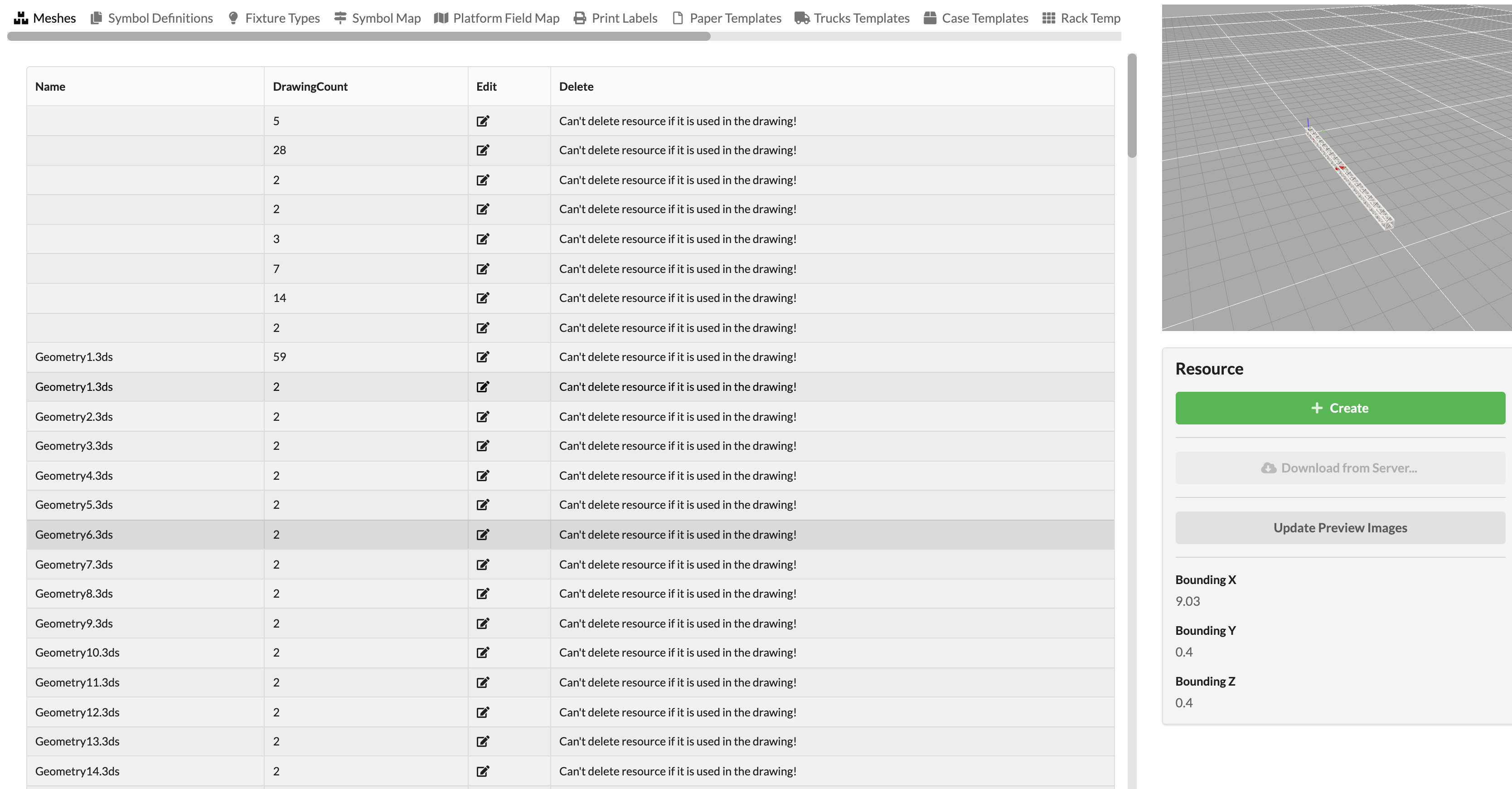
The left window pane contains a tabular overview with various commands. On the right side you can see the 3D preview of the geometry selected in the overview in the small renderer window. You will also find the maximum dimensions of the geometry at the bottom (Bounding).
Under the renderer window to the right, you can to create new geometries (Create) or import them from the online library into the drawing library (Download from Online Server). The Update Preview Images command updates any existing preview images present in the overview to the left.
In the overview table you can see how often the geometry is being used in your drawing.
You have the option of editing or deleting the geometry. However, the latter is only possible if it has been previously deleted in the drawing, i.e., the Drawing Count is 0.
This tab lists all symbols that exist in the drawing or have been imported into the drawing library. Symbols are intelligent objects that consist, for example, of geometries and other objects such as electrical connections and similar objects.
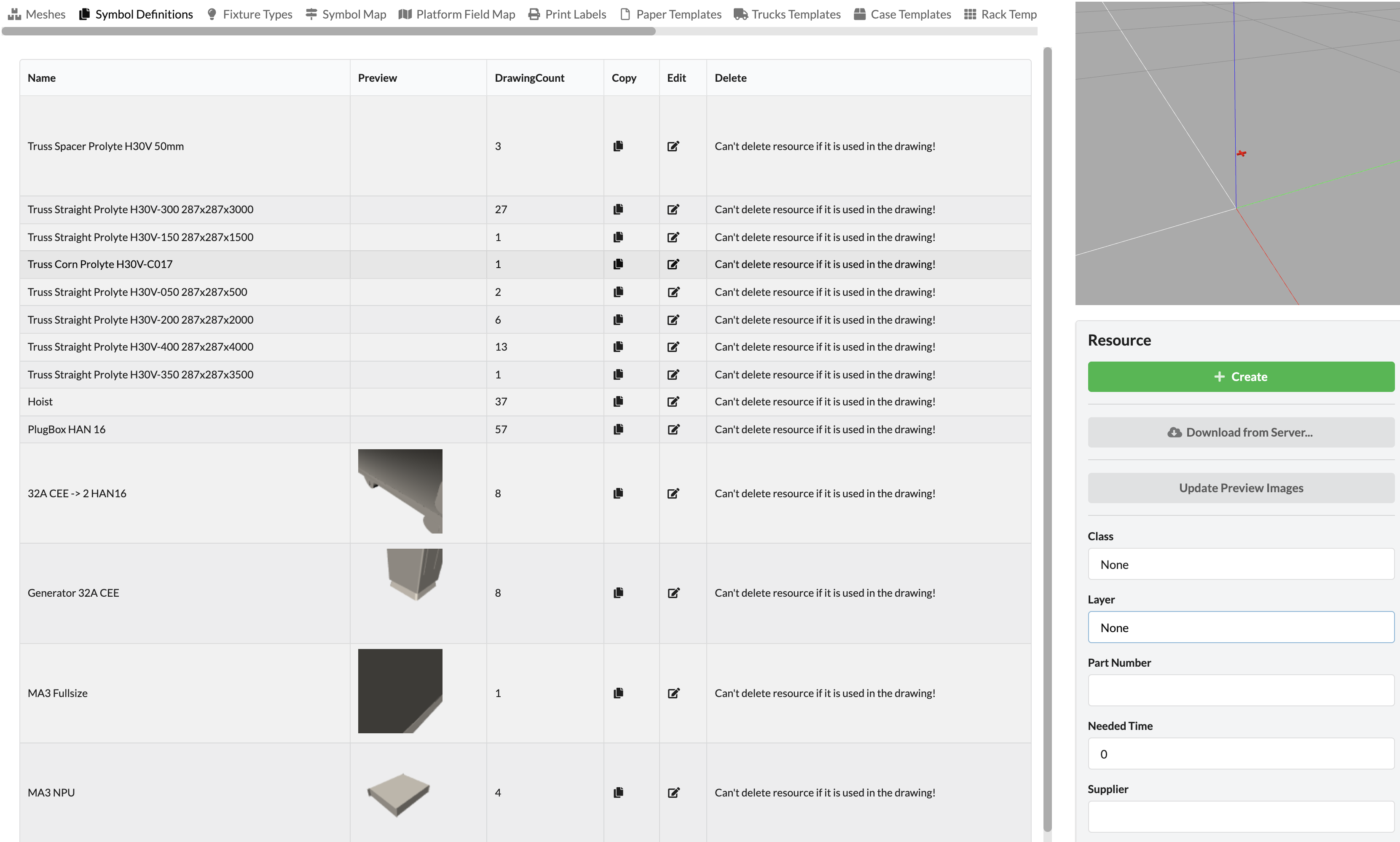
The left pane displays the tabular overview with various commands. To the right, the small renderer window displays the 3D preview of the icon activated in the overview.
Under the renderer window to the right, you can create new objects (Create) or import objects from the online library into the drawing library (Download from Online Server). The Update Preview Images command updates any preview images in the overview to the left.
More detailed information about building symbols can be found here.
In the overview table you can see how often the object has been used in your drawing.
You have the option to duplicate the object (Copy), edit it (Edit) or delete it. However, the latter is only possible if the object in the drawing has been deleted, i.e., the Drawing Count is 0.
This tab lists all fixtures that exist in the drawing or have been imported into the drawing library. Fixtures are symbols with additional lighting information created in them.
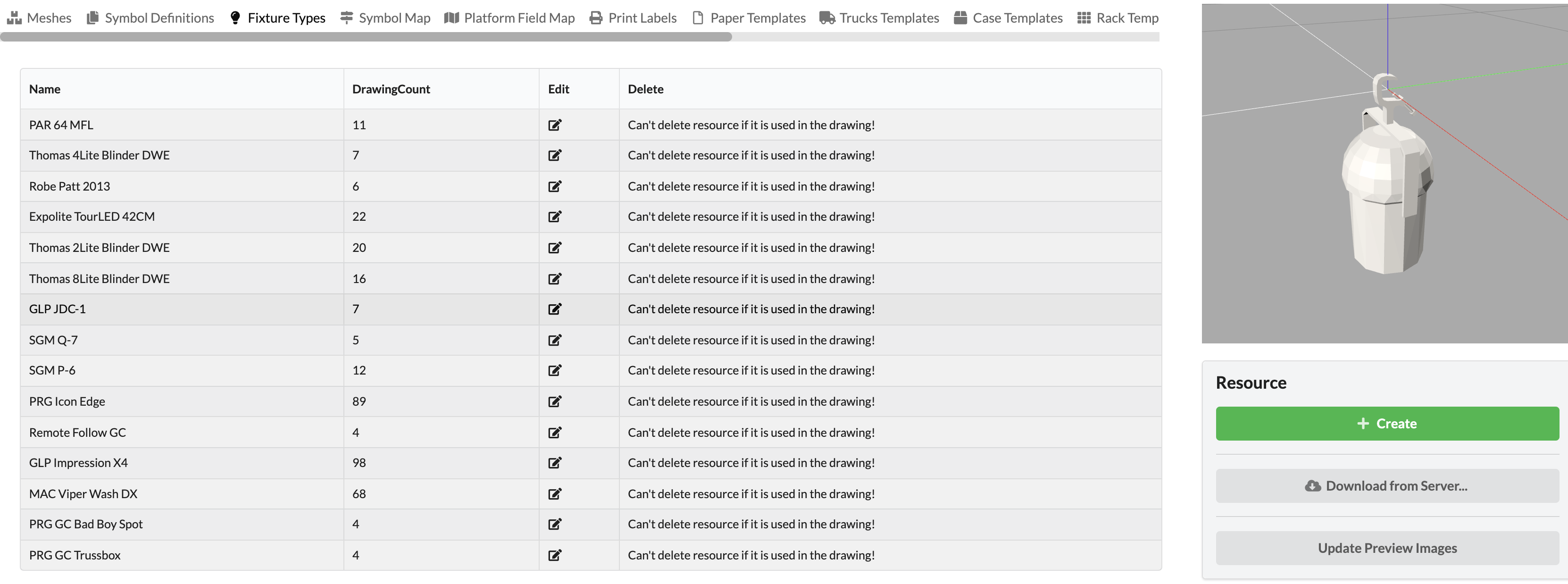
The left pane displays the tabular overview with various commands. To the right, you can see the 3D preview of the fixture activated in the overview in the small renderer window.
Under the renderer window to the right, you can create new objects (Create) or import objects from the online library into the drawing library (Download from Online Server). The Update Preview Images command updates any preview images in the overview to the left.
In the overview table you can see how often the object has been used in your drawing.
You have the option to duplicate the object (Copy), edit it (Edit) or delete it. However, the latter is only possible if the object in the drawing has been deleted, i.e., the Drawing Count is 0.
To optimize the functionality and performance of Production Assist, imported symbols from MVR files can be replaced by Production Assist symbols. There is already an import dialog for this when importing the MVR. In addition, the mapping - i.e., the specification of which symbol should be replaced with which Production Assist symbol - can be viewed, supplemented or deleted in the Resource Manager.
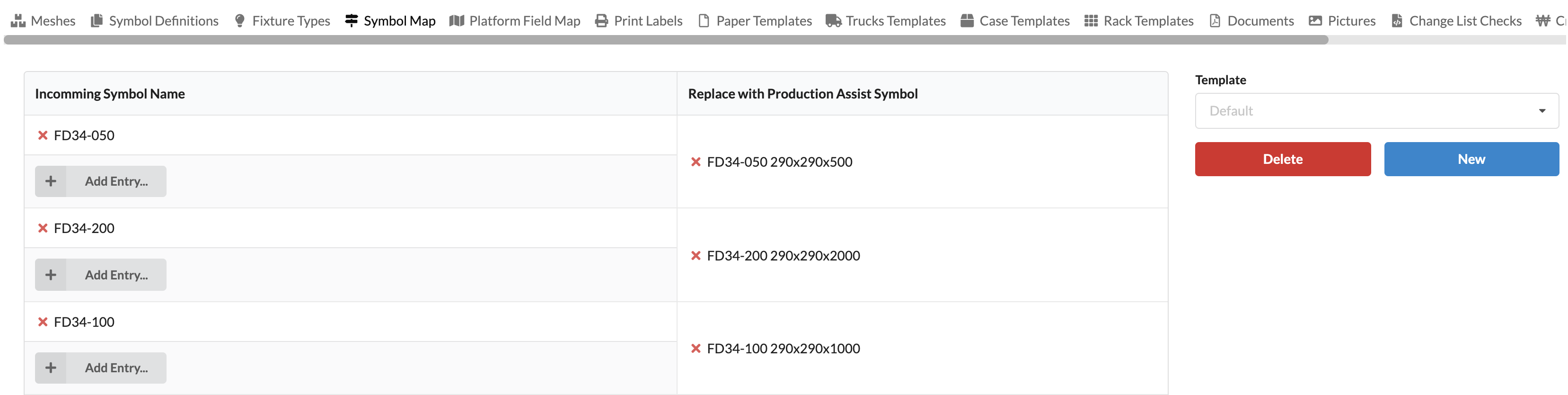
In the left area of the window, you can see which mappings have already been created. You can delete them by clicking on the red X in front of the symbol names. New replacement templates can be created via Add Entry.
A window opens in which the sybol to be replaced (Incoming Symbol Name) and the replacement symbol (Replace with Production Assist Symbol) must be selected.
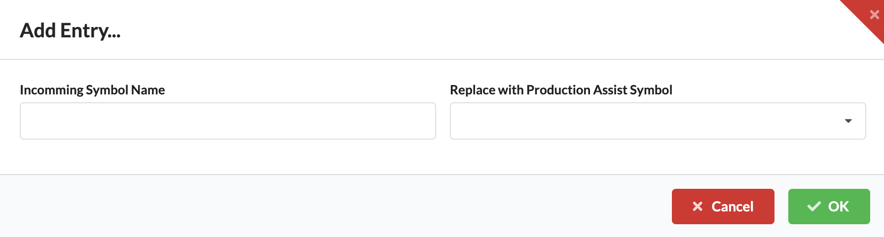
Upon importing next, this selection is already defined in the import dialog.
On the right side of the window, templates for Symbol Maps can be created and deleted. To do this, create a new template via New and adjust it on the left side. Each change is written to the currently selected template. You can then retrieve them repeatedly in the list later.
This can be of help, for example, if you get files from different customers that are to be replaced differently.
Delete can also be used to remove unnecessary templates.
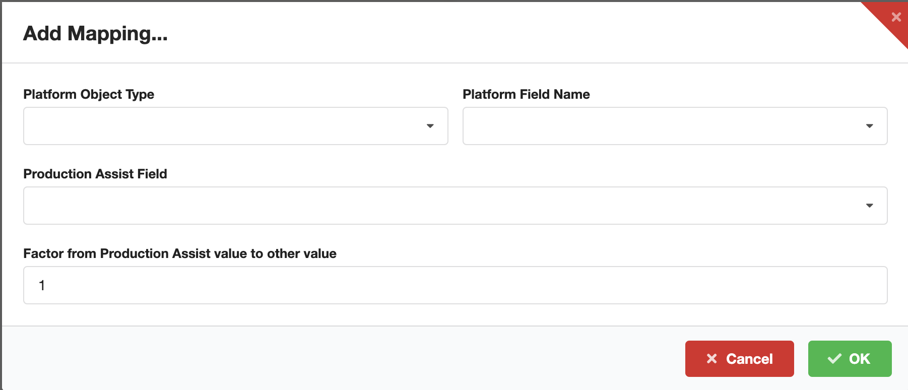
The Platform Field Map tab gives you the option, if you are using Production Assist as a plug-in with Vectorworks, to link the information fields of Vectorworks with those of Production Assist. To create a new shortcut, click Add Mapping.
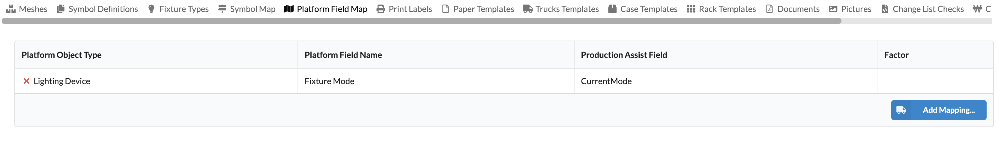
Under Platform Object Type you select the object type whose entry you want to link to a Production Assist field, e.g., spotlights, trusses, etc., and under Platform Field Name, the name of the info field. You select which field this is to be linked to in Production Assist under "Production Assist Field". Below this you can specify a factor by which the content of the field should be multiplied when linking.
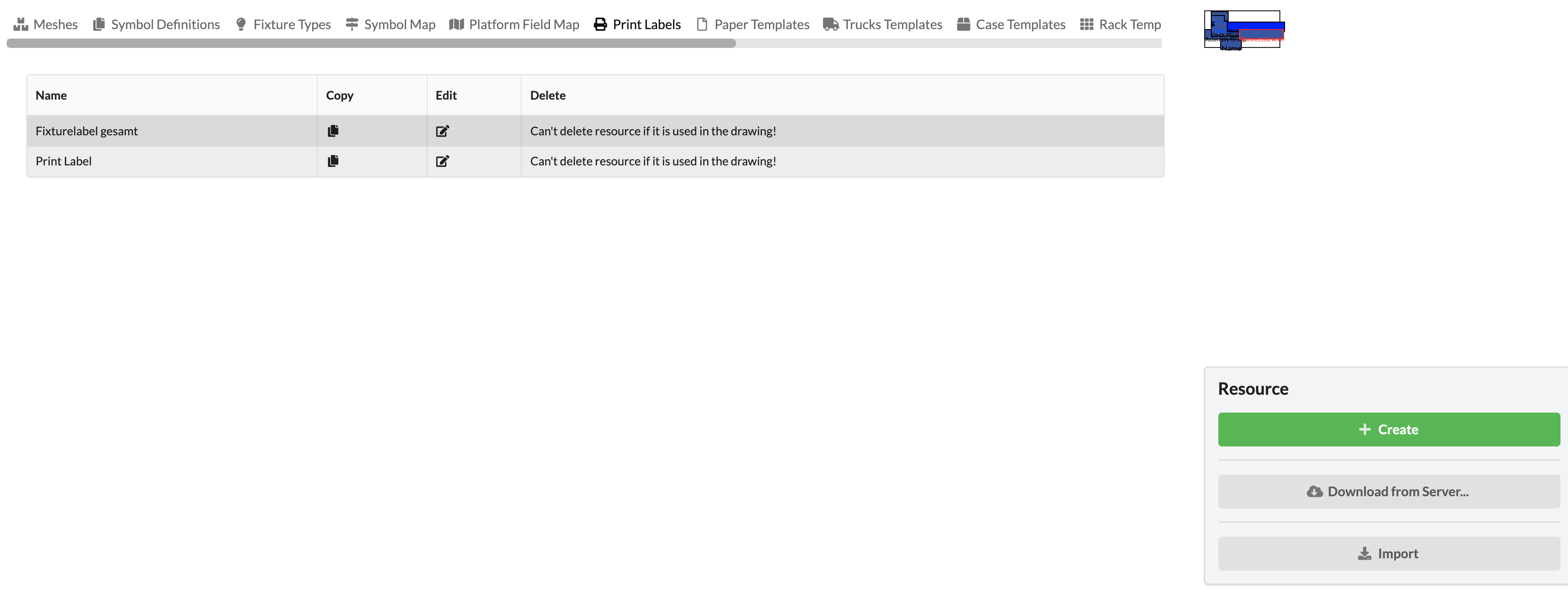
In the Print Label section, you can design different labels, which can contain information about all objects in your drawing, for example. You can print them out later and use them in production.
The left pane displays the tabular overview with various commands. You will see the name of your label and can duplicate (Copy), edit (Edit) or delete it (Delete).
To the right, you will see a schematic preview of your label. You can also design new labels (Create) or import them from the online library (Download from Server).
A more detailed guide on how to design labels can be found in the chapter Label Creation.
While the structure/information of the individual labels are defined in the Print Label tab, the Paper Templates tab is where you create the size of the labels and their orientation on the paper for later export as PDF and subsequent printing. Here you can see your already created templates with their values. They can also be deleted by clicking the red X in front of the name.
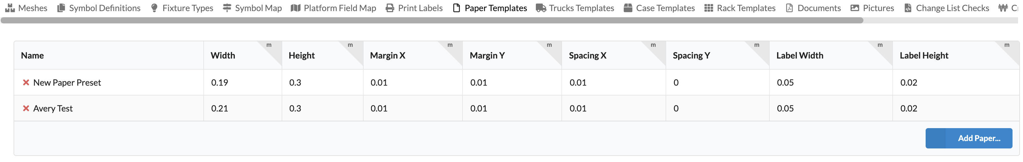
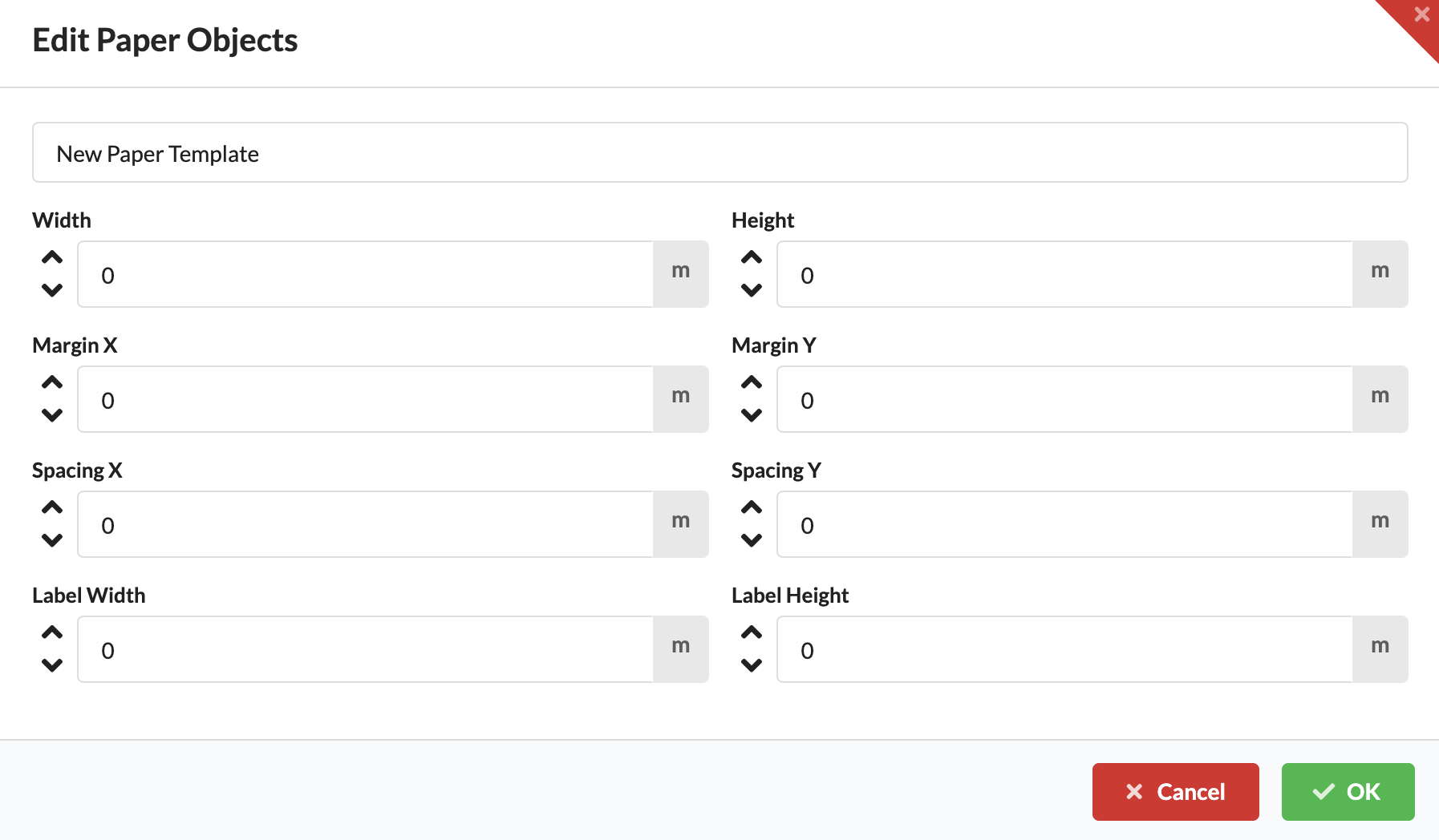
You can create a new template via Add Paper. There you enter the name of the template first.
| Feldname | Information |
|---|---|
| Width & Height | Width & height of the paper |
| Margin X / Y | Right/left (X) and top/bottom (Y) margins |
| Spacing X / Y | horizontal (X) and vertical (Y) spacing between labels |
| Label Width & Height | Width & height of the labels |
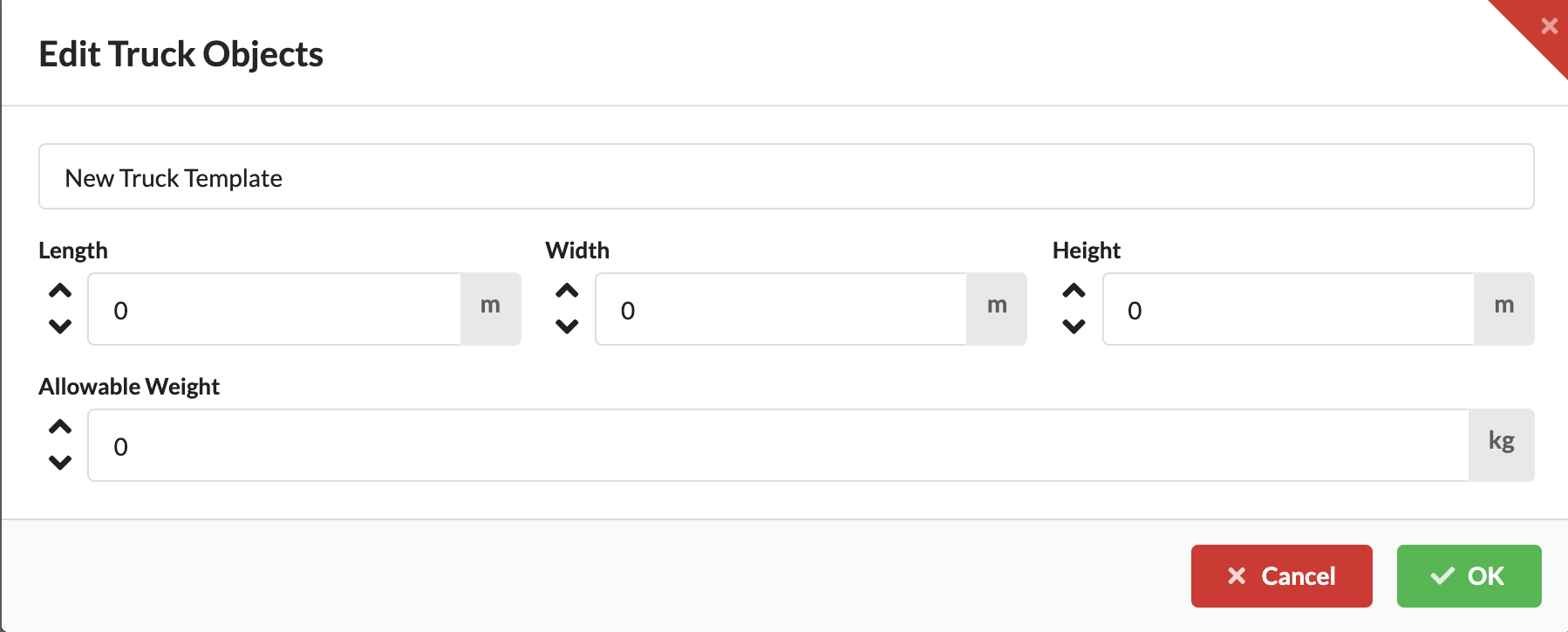
In Truck Templates you can define templates for trailer types, with which you can then create the required number of different trailers in the Navigation. In the tab you will see all already saved templates with their values. They can also be deleted by clicking the red X in front of the name. You create a new template via Add Truck.
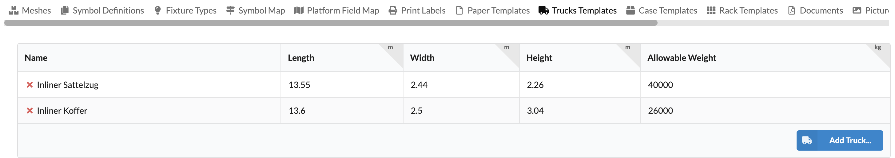
Here you can specify the name of the trailer type as well as the width, height, depth and allowable load weight of the trailer.
In Case Templates you can define templates for case types and their content, with which you can then create the required number of different cases in the Navigation. In this tab you will see all templates already saved along with their values. These can also be deleted via the red X in front of the name.
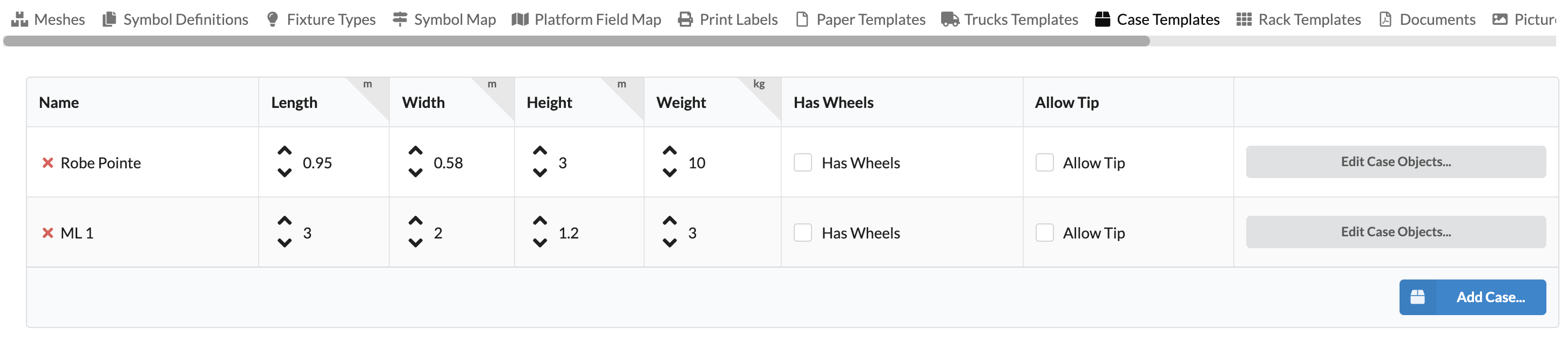
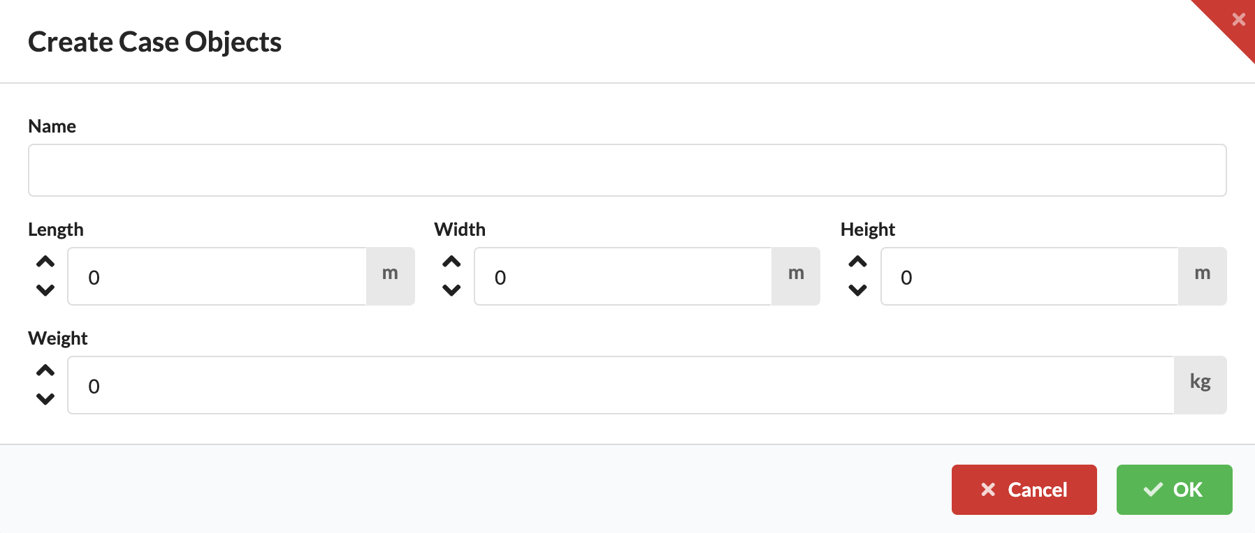
You create a new template via Add Case.
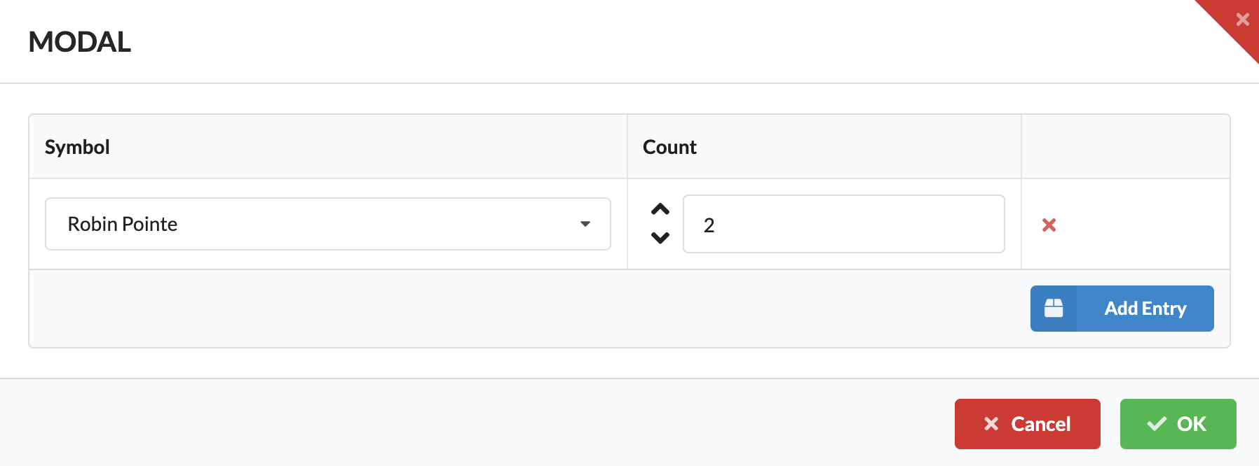
With Edit Case Object you can define which objects can be packed into the case.
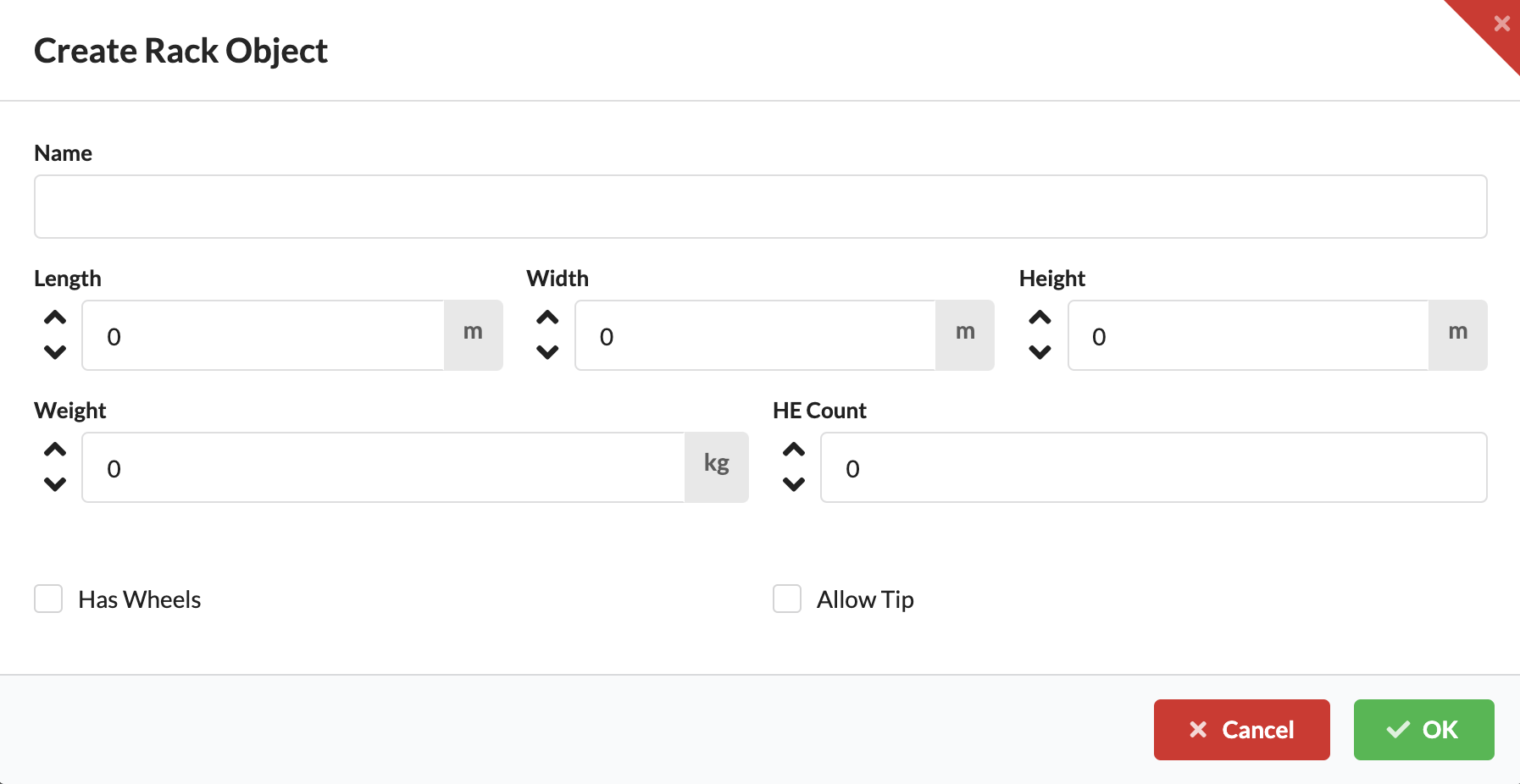
In Rack Templates you can define templates for rack sizes, with which you can then create the required number of different racks in the Navigation. In this tab you will see all templates already saved along with their values. They can also be deleted by clicking the red X in front of the name. You create a new template via Add Rack.
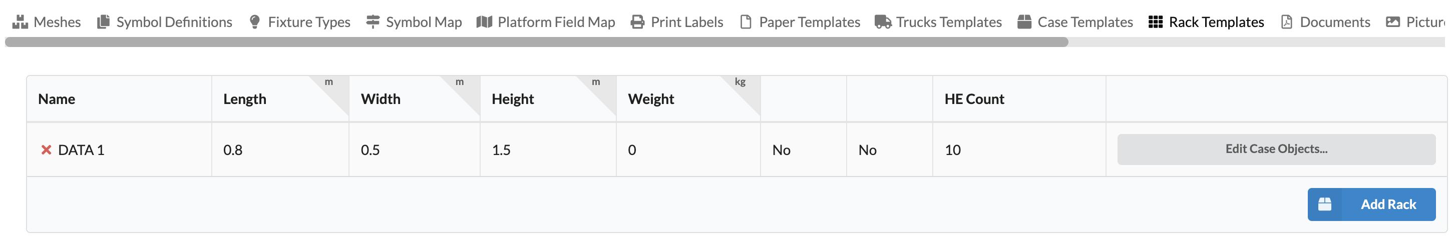
Then you enter the name, size, HE count and dead weight and whether the rack has wheels or whether it can be tipped on the truck. This information is important for truck planning.
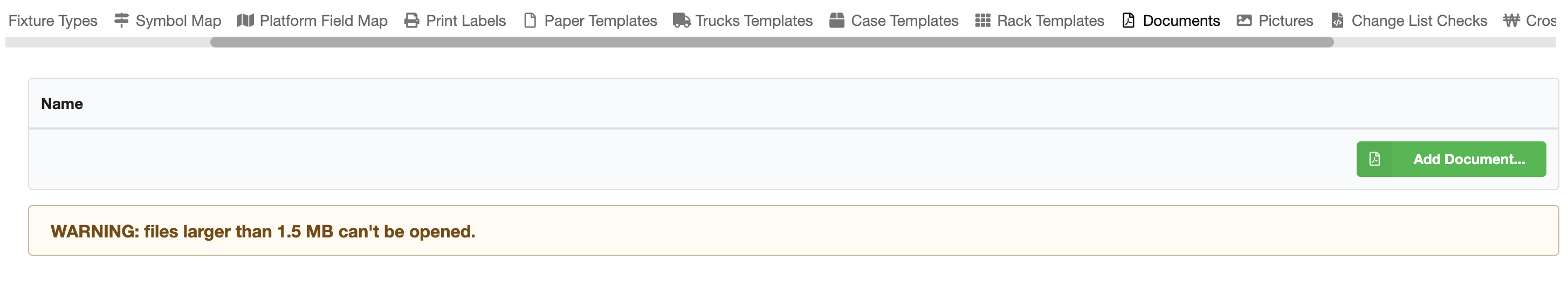
You can store documents in Production Assist, which you can then link to objects in the drawing. For example, test protocols for motors.
coming soon...
coming soon...
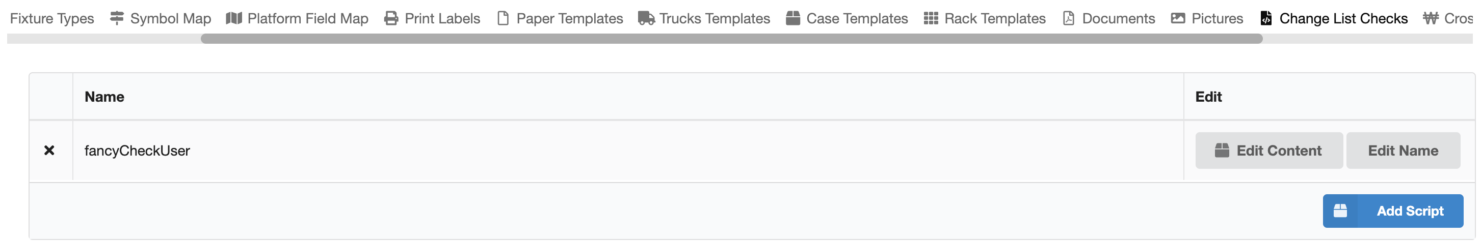
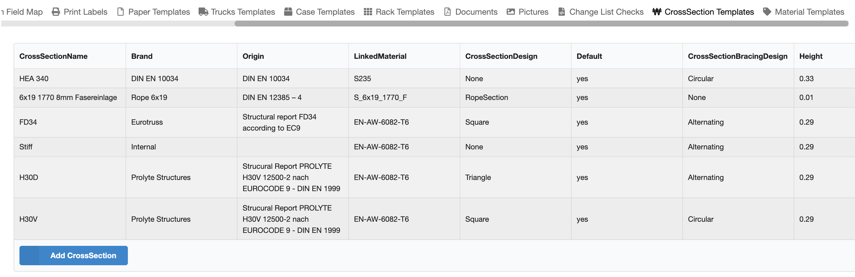
All cross-sectional data for structures are stored and managed here.
Use the Add Cross Section button to add a new cross-section and then edit all values in the table.
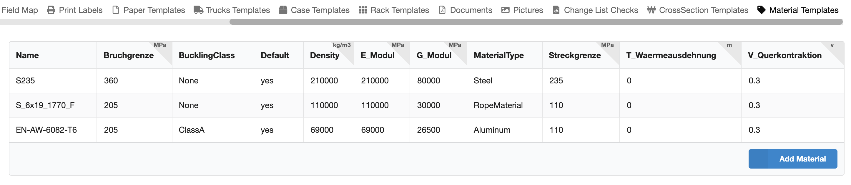
In this area you can store and manage different materials for support structures.
Use the Add Material button to add a new material item and then edit all values in the table.